
User manual


User Manual - English
14
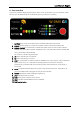
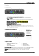
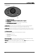
6. User Interface
Though the interface display appears simple, there is a lot of information you can read back, which
will help you troubleshooting and understanding how your device is operating.
1.
BATTERY
Only works on the Micro series. Indicates battery-life of the device.
2.
SIGNAL
Will stay always on, except on the Micro, where it warns about battery-life
3.
SIGNAL STATUS
On a transmitter, indicates the power output in mW. Full bar indicates
500mW, two green LEDs indicates 375mW (EU max.), one green LED indicates 100mW (DE
max.), yellow LED indicates 25mW.
On a receiver, indicates signal strength.
4.
TX
Device operating as a transmitter.
5.
RX
Device operating as a receiver.
6.
LINK
On a transmitter, it states it’s ready to establish a link. On a receiver, if off, indicates it’s
got no active link, if on, it indicates it’s already paired to a transmitter. If blinking
intermittently, it indicates that it has lost its link [either the transmitter is out-of-range or
turned off].
7.
DATA
It indicates whether data is being sent to the transmitter/receiver. If the LED is off,
check if the DMX cable is plugged correctly to the transmitter.
8.
MODE
Indicates the CTRL mode [See chapter 3.4].
9.
UNV
Indicates double-up mode.
10.
PWR
States power condition of the device.
11.
RDM
Indicates whether RDM is active or disabled.
12.
Red function button.
1
2
1
3
2
1
4
5
6
8
10
7
9
11
12