W-DMX ™ G5 USER MANUAL B L AC K B OX W H I T E B OX MICRO P R O B OX L a te s t rev i s i o n : S e p te m b e r 2 0 1 9 w w w.w i re l e s s d m x .
User Manual - English This page was intentionally left blank.
User Manual - English W-DMX™ G5 User Manual Issue date: 2019-09 Edition: 3rd Edition Subject to modifications. All trademarks referenced are trademarks or registered trademarks of their respective owners, whose protected rights are acknowledged. Copyright Wireless Solution Sweden Sales AB Wireless Solution Sweden Sales AB Stureparksvägen 7 451 55 Uddevalla Sweden Tel.: +46 522 511 511 Fax: +46 522 440 885 E-Mail: helpdesk@wirelessdmx.com Web: www.wirelessdmx.
User Manual - English TABLE OF CONTENTS 1. RADIO COMPLIANCE INFORMATION ............................................................................... 5 2. WARRANTY ............................................................................................................................ 6 3. YOUR WIRELESS DMX G5 SYSTEM .................................................................................... 7 4. THE W-DMX™ TECHNOLOGY ...........................................................................
User Manual - English 1. Radio Compliance Information FCC IDENTIFIER: NY2-WDMXTRX Name of Grantee: Wireless Solution Sweden Sales AB Equipment Class: Part 15 Spread Spectrum Transmitter FCC Rule Parts: 12C2402.0 General Notes: The antenna(s) used for this transmitter must be installed to provide a separation distance of at least 20 cm from all persons and must not be co-located cooperating in conjunction with any other antenna or transmitter. Users and installers must comply with operating manual.
User Manual - English • • • • • Within hospitals, health centers or any health care institution providing patient treatment with specialized staff and equipment. Hazardous Areas of classes I, II and III Exclusion Zones United States National Radio Quiet Zone Within an airplane or a vehicle No warranty or liability claim is possible in case the Product has been used outside of its reasonably intended usage area, as exemplified above. The Product must be operated with the factory default settings.
User Manual - English 3. Your Wireless DMX G5 System Welcome to the Wireless DMX family! We hope you enjoy your brand new devices – Wireless Solution is the industry’s leading system for transmitting and receiving DMX signals reliably, and we thrive on avid users like you who use our products.
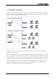
User Manual - English 4. The W-DMX™ Technology W-DMX™ is solely engineered by Wireless Solution Sweden to provide the same quality, reliability and performance as any wired DMX link. The technology allows you to establish point-to-point links, point-to-multipoint and multipoint-to-multipoint: W-DMX™ is unique in its use of advanced radio technologies that are also used in mobile phones and military communication.
User Manual - English 5. Operation All W-DMX™ devices share the same user interface – these instructions apply to all products: 5.1. Basic setup – Linking devices A basic setup is defined by the link between two devices. This means that, in order to send data from a transmitter to a receiver, it’s necessary to pair the devices: Press the red function button, on the transmitter, for 1 second, until the LINK LED starts flashing.
User Manual - English 5.4. Switching FLEX mode All units identified as a transceiver can be changed between transmitter or receiver – the units capable to operate in both modes are listed in chapter 2. FLEX mode determines if the unit is used in transmit mode (TX) or receive mode (RX): 1. 2. 3. 4. Disconnect the power cable Press and hold the red function button on the front panel. While holding the button, reconnect the power cable. Release the red function button.
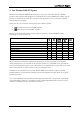
User Manual - English You can change between modes are any given moment – changes must be made to the transmitter: 1. Press and hold the red function button for 10 seconds 2. The top 4 LEDs will chase. Tap the red function button to scroll through all the modes. 3. There are 9 options available – you can understand the mode as follows: MODE LED UNV LED G3 2.4 GHz G4S 2.4 GHz G4S 5.8 GHz G5 2.4 GHz G5 5.8 GHz G5 5.2 GHz G5 2.4 GHz Double-Up G5 5.8 GHz Double-Up G5 5.2 GHz Double-Up 4.
User Manual - English 5.6. Enabling 5 GHz Due to the different regulations worldwide, all W-DMXTM devices come with 5 GHz disabled from front-interface control. This must be enabled with the W-DMXTM Dongle and Configurator software, available from the website. Once on, you may be able to scroll through all modes. 5.7. Double-Up Mode To enable Double-Up mode make sure that your W-DMX™ G5 has got the latest firmware. Please contact our helpdesk for guidance.
User Manual - English 5.10. RDM As default, all products come with RDM disabled. This must be enabled with the W-DMXTM Dongle and Configurator software, available from the website. The changes must be done on the transmitter and on each receiver that needs to downstream RDM. NOTE: R-512 units are not capable of receiving/transmitting RDM, as they do not have any transmitting capabilities to ping RDM back to the controller. 5.11.
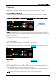
User Manual - English 6. User Interface Though the interface display appears simple, there is a lot of information you can read back, which will help you troubleshooting and understanding how your device is operating. 4 2 1 1 6 3 2 1 8 10 5 7 9 11 12 1. BATTERY Only works on the Micro series. Indicates battery-life of the device. 2. SIGNAL Will stay always on, except on the Micro, where it warns about battery-life 3. SIGNAL STATUS On a transmitter, indicates the power output in mW.
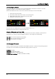
User Manual - English 7. Hardware 7.1. BlackBox Series 1 2 3 7 5 4 6 1. AC Power Supply connector, standard PowerCon® 20A Uac =110-240V / 50-60 Hz (for other voltage and frequency options, contact manufacturer) 2. EtherCon RJ45 port NOTE Ethernet port and power-over-ethernet power supply. Options to be purchased separately – contact manufacturer. 3. 4. 5. 6. 7.
User Manual - English 7.2. WhiteBox Series 1 XLR1 XLR2 2 3 4 5 1. Overlay connector 2. DMX input and/or output 3. Ethernet RJ45 port NOTE: Ethernet port and power-over-ethernet power supply. Options to be purchased separately – contact manufacturer. 4. DC Power Supply Connector, Standard 5.08mm NOTE: 12V DC power supply [ - / + ] ±20%, reverse polarity protected from UL/ETL certified, limited power supply (LPS) rated 12VDC, 1.25A max. (to power from 12V batteries, contact manufacturer).
User Manual - English 7.2.2 WhiteBox installation guide Installing the WhiteBox series does not require special tools – we recommend installing in a suitable location, like a flat surface. Please take care when installing and, in order to achieve best results, the transmitter and receiver must be in line-of-sight of each other. Insert the back plate into the wall mount screws (Fig. 1) and slide the WhiteBox down to fix it into place (Fig. 2). Once adjusted, the WhiteBox should fix into place.
User Manual - English 7.2.3 Mains Wire installation and termination Install the mains wire through the cable gland above shown (Fig. 4 and 5). Cable gland is M16x1.5 type, outer cable diameter should be between 4mm and 8mm. All glands shall be mounted and tight, or closed with a gland cap if not in use. If not closed, it may create condensation inside the box and damage the electronics, and will not be covered by warranty. The mains connection is a 3-pole 5.
User Manual - English 7.2.4 Contents included When you purchase a new ProBox, the following items are included: • • WhiteBox device (F-1 or F-2) User Manual • • 3dBi Antennae DC connector Working Temperature: -20o to 45o Celsius, storage temperature -20º to 50º Celsius. Max. humidity 90%. IP 66. Pre-heat is needed for temperatures lower than -5ºC – the product should not be shut down in freezing conditions, in order to prevent power-supply failure and/or complete inability to operate.
User Manual - English 7.3. Micro Series 2 1 3 4 1. Kensington security slot 2. XLR female 5 pin (Female on R-512 models, male for F-1 models) 3. Power switch Power switch only works when operating with batteries, not with USB power. 4. Micro USB 5V power connector Power supply function only, 5DVC ±10%/500mA max. BATTERY-TYPE: This product works with 4x AAA batteries. The product accepts rechargeable batteries, although does not recharge them when plugged to its USB power-supply.
User Manual - English 7.4. ProBox Series 7.4.1 ProBox F-2500 Double-Up explained G3/G4S/G5 Mode: 1. Universe 1 In 2. Inoperative 3. Universe 2 In 4. Inoperative Double-Up Mode: 1. Universe 1 In 2. Universe 2 In 3. Universe 3 In 4. Universe 4 In G3/G4S/G5 Mode: 5. Universe 1 Out 6. Inoperative 7. Universe 2 Out 8. Inoperative Double-Up Mode: 5. Universe 1 Out 6. Universe 2 Out 7. Universe 3 Out 8. Universe 4 Out 9. DC Power Supply Connector, Standard 5.
User Manual - English 8. Upgrades and Updates 8.1. Ethernet Upgrade You can find how to do the ethernet upgrade in a separate guide, under www.wirelessdmx.com/download 8.2. Firmware Update Wireless Solution is committed to developing and improving its wireless technology – though firmware updates are not constant, occasionally there is a need to release a new version, whether related to the transmission itself, glitches with the interface or RDM implementation.
User Manual - English 8.3. W-DMX™ Configurator To understand the use of our W-DMX™ dongle, you need to know how wireless works. Wireless transmission is like a highway with 13 lanes, where most traffic happens on channels 1, 6 and 11, leaving plenty of room for operating a Wireless DMX system. This condition is specific to wi-fi traffic, for transmitting normal internet over wireless – this is because these channels do not overlap, like having lanes with no traffic.
User Manual - English 8.4. ArtNet Browser Before starting, please note that not all products come with ArtNet as standard. If you haven’t purchased the ArtNet extension, your product does not have ArtNet enabled. Download the W-DMX™ Brower: www.wirelessdmx.com/download Launching Browser Remember to physically connect your device to your computer or network (with a CAT5 cable)! Get going in three easy steps: 1.
User Manual - English IP Addressing Communications between the computer and the device is over IP. This is the same for all lighting control protocols, e.g. Art-Net and Streaming ACN. Each device on the network must have its own unique IP address. Two devices (e.g. a computer and a dongle) directly connected to each other, whether via an Ethernet cable or over a switching hub, must be in the same IP address range (known as the “subnet”).
User Manual - English 9. Recommendations There are several tips and tricks that could make your wireless transmission work better. Here’s a few that should be followed: Fig.1: It’s important that all antennas point to the same axis – wireless waves have a radial pattern that should be valued. There are a number of accessories that can help maintaining directionality. Fig.2: There are limitations to how wireless waves propagate through air.
User Manual - English Fig.3: Micros like to be seen – just because it’s small, don’t throw it inside a box! They have a very sensitive antenna that doesn’t like barriers. And most of all, always point their display to each other – that’s where their optimum performance is! Multiple Transmitters If you have multiple transmitters sending data to multiple receivers, it’s worth masking out channels with the Co-Existence dongle, so they don’t end up interfering with each other.
h e l p d e s k @w i re l e s s d m x .