
User's Manual

Wireless Matrix SDT-5000 Installation and User Guide
Doc. 020-331-0002v1.1 16/31
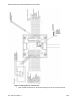
NOTE:
This opens up the metallic jaws in the rounded oval hole.
2. Insert the wire into the rounded oval hole.
3. Remove the screwdriver. The jaws clamp down on the exposed wire at the end of the
cable.
4. Repeat steps 1 through 3 for every wire in the cable that needs to be connected to the
terminal blocks.
5. Unused wires in the cable sheath should be neatly rolled up and taped or secured so no
electrical connection is made to the junction blocks.
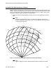
Aiming the Antenna
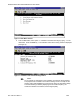
Using the Multi-meter and the RSSI to Aim the SDT-5000
When the SDT-5000 is first powered up it provides a voltage proportional to its receive signal
strength. The voltage is indicated on the receive signal strength indicator (RSSI) wire (white with
red stripe) or pin “9” on the DB9 connector on the cover of the junction box.
1. Connect the positive lead of the voltmeter to the RSSI wire and the negative lead to a
ground wire (white with black stripe).
2. Position the meter so the display is easy to view.
3. Power-up the SDT-5000. The RSSI voltage will rise and fall as the SDT-5000 is rotated.
4. Position the SDT-5000 so the RSSI voltage is at its maximum.
5. Rotate the SDT-5000 over a wide angel to ensure the maximum RSSI voltage has been
found. The RSSI should be greater than 2 V.
6. The RSSI voltage is only generated for a short period of time. If the RSSI voltage is no
longer displayed, power down the SDT-5000 and power it up again.
7. Once an optimal RSSI voltage is achieved, secure the bolts that lock the position of the
SDT-5000.