
User's Manual

Wireless Matrix SDT-5000 Installation and User Guide
Doc. 020-331-0002v1.1 11/31
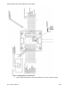
Attaching to a Free Standing Pole
1. An in-ground free standing pole installation will consist of a 10 to 12-foot
2 3/8 or 2 7/8-inch schedule 40 pipe installed in a hole filled with concrete.
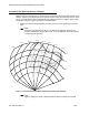
2. Identify the installation site keeping in mind that the location must be outside any hazardous
area and “unobstructed line of sight” to the satellite is essential.
3. Dig the hole at least 2-feet below the frost line where possible.
a. The top of the concrete should be at least 6-inches below the frost line.
b. The hole should be at least 12-inches in diameter.
4. In high wind areas, install a bolt or pipe in the bottom portion of the pole. This should
prevent the pole from turning in the concrete pad causing misalignment of the antenna or
solar panels and damage to the power-data cable.
5. Allow concrete to harden before proceeding with installation of antenna or solar panels.
6. Use proper sized pole brackets/U-bolts to affix antenna to pole.
7. Secure the cable with cable clamps or ties every 12 to 18-inches or run cable inside conduit
or Seal-Tite. Avoid tight bends and kinks in the cable and grounding cable. The
recommended tightest allowable bend radius is 2-inches.
Attaching to an Existing Structure (Meter Shed or
Compressor Building)
1. Use two 1.5-inch Kindorf or equivalent channel, bolted to shed or building support struts.
One to be installed near the bottom of the structure and the second to be installed near the
top of the structure.
2. Use Kindorf or equivalent pipe brackets (for 2 3/8 or 2 7/8 inch pipe) to affix pole to Kindorf
channel.
3. Use proper sized pipe brackets (for 2 3/8 or 2 7/8 inch pipe) to affix antenna base to pole.
4. Secure the cable with cable clamps or ties every 12 to 18-inches or run cable inside conduit
or Seal-Tite. Avoid tight bends and kinks in the cable and grounding cable. The
recommended tightest allowable bend radius is 2-inches.