
Installation Instructions
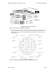
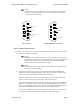
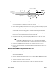
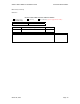
Table Of Contents

Wireless Matrix MBS2-LP Installation Guide Document MBUD-0088v1
March 04, 2004 Page 7
NOTE:
The RS-422 transceiver in the MBS2-LP unit is disabled when the MBS2-LP is
installed for use in RS-232 mode. As a result, it is acceptable to cut back the
unused RS-422 wires if desired.
Green
4
5
3
2
1
9
8
7
6
Brown
White/Green
White/Brown
Slate/White
4
5
3
2
1
9
8
7
6
Red/Blue
White/Slate
CSC Connector Test Port (Diagnostics) Connector
Figure 5. MBS2-LP DB9 Connectors
12. See figure 5 for the pin insertion locations. If the DB9 contacts must be removed for any reason,
use Amp tool No. 91285-1 or equivalent.
NOTE:
The DB9 Connector diagram in Figure 5 is looking at the back of the connector.
The backside is considered to be the side with the black plastic protruding and the
two pair twisted cable is to be inserted from this side. The front of the DB9
Connector only has the metal housing protruding.
NOTE:
Some hardware does not support DTR. For this hardware, the white/brown pin
should be routed to Pin 7 (RTS).
13. The CSC connector (see figure 5) is the port used by the Wireless Matrix MBS2-LP to
communicate with the Client Side Computer (CSC). This port allows the communication
between the Wireless Matrix MBS2-LP and the CSC to take place.
The CSC is a DB9 Female connector that uses four leads of the power-data cable (19 pin,
cannon connector) with the pin-out configuration as displayed in figure 5.
The Test Port (Diagnostics) connector (see figure 5) is the port used by the Wireless Matrix
MBS2-LP to communicate with the On Board Computer (OBC) module located within the
CSC for test and diagnostic purposes only. This port allows diagnostics capabilities between
the Wireless Matrix MBS2-LP and the user interface, such as HyperTerminal.
The Test Port is a DB9 Female connector that uses three leads of the power-data cable (19
pin, Cannon connector) with the pin-out configuration as displayed in figure 5.