
Installation Instructions
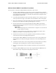
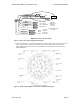
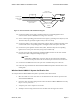
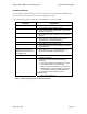
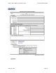
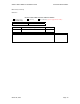
Table Of Contents

Wireless Matrix MBS2-LP Installation Guide Document MBUD-0088v1
March 04, 2004 Page 6
#22
Orange
/
/Red
#14
Black
#14
Red
IGN
Gnd
+13.6 V
#22
White
/Green
#22
Brown
#22
White
/Brown
#22
Green
RXD
TXD
DTR
GND
#22
White
/Slate
#22
Red
/Blue
#22
Slate
/White
OBC Port
contacts to be
inserted in
connector
Female D-sub Crimp
Contacts
PIN #2
PIN #3
PIN #4 OR 7
PIN #5
Test Port
contacts to
be inserted
in connector
PIN #2
PIN #3
PIN #5
RXD
TXD
GND
MBS2-LP Power-Data Cable (Detail)
Figure 3. Power-Data Cable Configuration Diagram
11. The shells and bodies are supplied separately and are attached to the cable after the unit cable is in
place. This allows the cable to be inserted through a smaller opening in the vehicle chassis.
Figure 4 displays the pinout of the factory-assembled connector that connects to the Wireless
Matrix MBS2-LP.
Figure 4. Wireless Matrix MBS2-LP Connector Configuration Diagram