
Installation Instructions
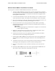
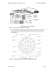
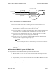
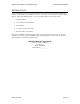
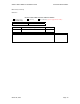
Table Of Contents

Wireless Matrix MBS2-LP Installation Guide Document MBUD-0088v1
March 04, 2004 Page 5
Wireless Matrix MBS2-LP Installation Procedures
The average time for the Wireless Matrix MBS2-LP installation is about an hour.
1. The Wireless Matrix MBS2-LP is mounted using 1/4-inch x 20 tpi (threads per inch) bolts
screwed into its base. The threaded portion in the base is a maximum of 1/2-inches deep. To
prevent damage during installation, care should be taken that the thread engagement of the
mounting bolt be 1/2-inch or less.
2. Locate the desired installation location on the vehicle (ideally on an area where the antenna
will be exposed from all angles, as described in Antenna Installation section of this guide).
3. Place a piece of duct tape over the area to drill, for the antenna mount bolts and cable access
(this will prevent the drill bit from sliding and damaging the roof surface).
4. Place the antenna mount’s (refer to the appendix for the Wireless Matrix part number)
mounting bracket on the desired location and mark the four drilling points (use bracket as a
template for bolt locations).
NOTE:
Avoid drilling through wires, mounted fixtures or equipment. Secure the bracket
to vehicle supports or framing.
5. Drill the four 5/16-inch holes for the antenna mount, as marked by the template, and an
additional 1/2-inch hole at a selected location for cable access.
6. Install the antenna mount’s (refer to the appendix for the Wireless Matrix part number)
antenna bracket with its corresponding mounting hardware.
7. Install the Wireless Matrix MBS2-LP to the antenna mount’s (refer to the appendix for the
Wireless Matrix part number) mounting plate with the three 1/4-inch mounting bolts and
washers.
8. Assemble the antenna mount’s (refer to the appendix for the Wireless Matrix part number)
mounting plate to the mounting bracket and secure with the mounting hardware.
9. Place the 1/2-inch grommet into place (around the cable hole) to protect the cable from
damage.
10. The Wireless Matrix MBS2-LP power-data cable is supplied without the DB9 bodies and
shells installed. Figure 3 displays the wiring diagram for this cable.
Power-Data Cable