Wireless Matrix MBS2-LP Installation Guide Wireless Matrix Corporation 12369-B Sunrise Valley Drive, Reston, VA 20191 Phone : (703) 262-0500 FAX : (703) 262-0380 www.wirelessmatrixcorp.com Document Number MBUD-0088v1 Version 1.
Wireless Matrix MBS2-LP Installation Guide Document MBUD-0088v1 MBS2-LP Installation Guide Copyright © 2005 Wireless Matrix Corporation. All rights reserved. Printed in the United States of America This document is proprietary to Wireless Matrix Corporation. Do not reproduce, use or disclose without permission. We have made every effort to ensure the accuracy of all information contained in this document.
Wireless Matrix MBS2-LP Installation Guide Document MBUD-0088v1 Wireless Matrix MBS2-LP Installation Guide TABLE OF CONTENTS REGULATORY STATEMENTS ....................................................................................................................... IV OTHER SAFETY PRECAUTIONS .................................................................................................................... V INTRODUCTION...................................................................................
Wireless Matrix MBS2-LP Installation Guide Document MBUD-0088v1 Regulatory Statements Read and understand the entire manual and follow the safety instructions. The following regulatory approvals apply for the Mobile Base Station 2 Low Profile (MBS2-LP): • FCC • IC • PTCRB FCC Part 15 Compliance This device complies with Part 15 of the FCC Rules. Operation is subject to the following two conditions: 1. This device may not cause harmful interference 2.
Wireless Matrix MBS2-LP Installation Guide Document MBUD-0088v1 Other Safety Precautions Read and understand the complete Installation Guide, including the Safety Precautions, prior to using the MBS2-LP Modem. The MBS2-LP is a radio unit used to receive and transmit data. When in operation, the MBS2-LP transmits and receives RF signals to and from a Geo-stationary orbital satellite. The MBS2-LP must be used in accordance with the safety guidelines stated in this document.
Wireless Matrix MBS2-LP Installation Guide 7. Document MBUD-0088v1 Pay close attention to the electrical power installation requirements described in this guide. Failure to comply with the described section could result in serious damage to the electrical system of the vehicle. .
Wireless Matrix MBS2-LP Installation Guide Document MBUD-0088v1 MBS2-LP Installation Guide INTRODUCTION This guide explains procedures for installing the Wireless Matrix Mobile Base Station 2 – Low Profile (MBS2-LP) modem. The guide does not provide detailed installation instructions for every type of vehicle. Instead, because of the variety of available vehicle makes and models, it outlines the installation process and allows the installer to choose appropriate options.
Wireless Matrix MBS2-LP Installation Guide Document MBUD-0088v1 General Considerations • Check for wires or obstructions at the opposite side of any panel in which you intend to drill. • Stay at least 20 inches away from an operating antenna when you are above the level of the antenna base. • Do not remove the antenna cover. Removing the antenna cover will void the product warranty. • Do not paint the antenna. Paint on the antenna will void the product warranty.
Wireless Matrix MBS2-LP Installation Guide Document MBUD-0088v1 INSTALLATION OVERVIEW Installation Installing the Wireless Matrix MBS2-LP is not difficult, but you must consider the variables involved, such as, the truck type and location of existing equipment. Installation time can vary depending upon the installer’s experience and the vehicle design. While a single individual can perform most installation operations, certain procedures may require the help of a second person.
Wireless Matrix MBS2-LP Installation Guide Document MBUD-0088v1 INSTALLATION INSTRUCTIONS The following instructions explain the processes for installing the antenna, power-data cable and the power extension cable. The installation process may vary slightly if the vehicle’s design or accessories will not permit the execution of the steps outlined below. Antenna Installation Ensure there is not a height obstruction. Mount the antenna so that it is level.
Wireless Matrix MBS2-LP Installation Guide Document MBUD-0088v1 Wireless Matrix MBS2-LP Installation Procedures The average time for the Wireless Matrix MBS2-LP installation is about an hour. 1. The Wireless Matrix MBS2-LP is mounted using 1/4-inch x 20 tpi (threads per inch) bolts screwed into its base. The threaded portion in the base is a maximum of 1/2-inches deep. To prevent damage during installation, care should be taken that the thread engagement of the mounting bolt be 1/2-inch or less. 2.
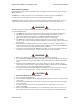
Wireless Matrix MBS2-LP Installation Guide Document MBUD-0088v1 IGN #22 Orange /Red #14 /Black Gnd +13.6 V #14 Red #22 White /Green RXD TXD DTR #22 Brown #22 White /Brown #22 Green #22 White /Slate #22 Red /Blue #22 Slate /White PIN #2 PIN #3 PIN #4 OR 7 GND PIN #5 RXD PIN #2 TXD GND PIN #3 PIN #5 Test Port contacts to be inserted in connector OBC Port contacts to be inserted in connector Female D-sub Crimp Contacts MBS2-LP Power-Data Cable (Detail) Figure 3.
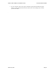
Wireless Matrix MBS2-LP Installation Guide Document MBUD-0088v1 NOTE: The RS-422 transceiver in the MBS2-LP unit is disabled when the MBS2-LP is installed for use in RS-232 mode. As a result, it is acceptable to cut back the unused RS-422 wires if desired. 1 1 6 2 White/Green 7 6 2 White/Slate 3 Red/Blue 7 3 Brown 8 8 4 4 White/Brown 9 9 5 Green CSC Connector 5 Slate/White Test Port (Diagnostics) Connector Figure 5. MBS2-LP DB9 Connectors 12.
Wireless Matrix MBS2-LP Installation Guide Document MBUD-0088v1 14. Run the antenna power-data cable (the end without connectors) from the top of the roof in to the cabin through the grommet, and route the cable in the inside of the vehicle as desired to reach the constant 12-volt power source. 15. Connect the power-data cable to the Wireless Matrix MBS2-LP by matching the connector grooves and twisting the connector to its locked position. 16.
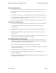
Wireless Matrix MBS2-LP Installation Guide Document MBUD-0088v1 Battery Pos. Red No 10 to 12 AWG 5 Amp Fuse To Battery Pos Battery / Ign Cable To Battery Neg To Ignition Recommended Battery/ Ignition Cable Battery Neg Black No 10 to 12 AWG Ignition White No 18 AWG Figure 6. Power Extension Cable Installation Diagram 20. Connect the ignition sensor (white, 18 AWG lead) to its corresponding ignition fused connector at the vehicle’s distribution box using a fuse connector. 21.
Wireless Matrix MBS2-LP Installation Guide Document MBUD-0088v1 Potential Problems The most common problems with the CSC are power connections and configuration. PLEASE consult your information services department for details in configuring your CSC. Table 1 lists potential problems with the CSC and suggestions to correct the problems. Symptom The CSC does not power up. Suggestions a. Check that the power cable is properly connected to the antenna and the power source. b.
Wireless Matrix MBS2-LP Installation Guide Document MBUD-0088v1 WARRANTY Wireless Matrix warrants that upon shipment to Customer from supplier’s facility and for the Warranty Period, hereinafter defined, the Equipment shall be free from defective materials and faulty workmanship and capable of accessing the Service ("Good Working Order").
Wireless Matrix MBS2-LP Installation Guide Document MBUD-0088v1 RETURN POLICY If the troubleshooting process in the Potential Problems section of this guide determines the modem to be defective, return the unit to Wireless Matrix for repair. Contact your service provider and request a Return Material Authorization (RMA) number. To receive an RMA number, be prepared to provide: 1. Customer Address 2. Contact Name and Phone Number 3. Serial Number 4. P.O # (If unit is out of Warranty) 5.
Wireless Matrix MBS2-LP Installation Guide March 04, 2004 Document MBUD-0088v1 Page 13
Wireless Matrix MBS2-LP Installation Guide Document MBUD-0088v1 RMA form (continued) RMA Form BELOW IS FOR COMPLETION BY WIRELESS MATRIX Dead on Arrival In Warranty Replacement Unit(s) Transceiver Serial # Date Received Out of Warranty (please supply Purchase Order) Antenna Serial # Failure Type (Category & Code) Date Shipped Problem Description and Actions Taken (Factory use Only) March 04, 2004 Date/Tech Initials Page 14
Wireless Matrix MBS2-LP Installation Guide Document MBUD-0088v1 APPENDIX - WIRELESS MATRIX MBS2-LP COMPONENT LIST Wireless Matrix MBS2-LP Component Name Part Number Wireless Matrix MBS2-LP Modem 906-xxx-xxxx or 907-xxx-xxxx Wireless Matrix MBS2-LP Cable Assembly Kit 800-120-0048 1/2-inch Grommets Antenna Mount, Low Profile with 1/4-inch Bolt and Nuts (Optional equipment) Regular 03-03-037 Adjustable 03-03-071 Low Profile 03-03-075 This Manual Required Components Cordless Drill Cable Connectors and