
User's Manual


Document Number 050-015-009R05
Wireless Mmatrix Proprietary and Confidential 9/20
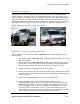
a. Carefully strip a small section of each wire (the battery, ignition, and
ground wires) found in their respective locations under the dashboard in
the vehicle.
b. Insert the end of each power cable wire through each corresponding
vehicle wire, and wrap the end around the vehicle wire.
c. Solder the connection.
d. Wrap the connections with electrician tape, and then cinch a cable tie
tightly around each connection, directly over the connection point.
e. Note that in the system diagram, the ignition wire is shown colored
white, the battery wire is shown colored red, and the ground wire is
shown colored in black, for ease of identification.
7. Insure that all the cables are secure and located at a distance from the
driver’s operational area.
External antennas
Communicator 1000C uses the following antennas:
1. Antenna A -CELL band: -1dBi≤ gain ≤2dBi
-PCS band: -1dBi≤ gain ≤3dBi
2. Antenna B -CELL band: -1dBi≤ gain ≤2dBi
-PCS band: -1dBi≤ gain ≤3dBi
3. 802.11 antenna (monopole) -1dBi ≤gain ≤2.5dBi
4. GPS patch antenna with internal LNA. 16dBi ≤ gain ≤26dBi
Note: The max gain requirements for the antennas, does not include the cable losses
.
Antenna cable losses are: 1.3dB@ 850MHz, 1.9dB@1.9GHz and 2.3dB@2.45GHz
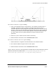
Antenna Installation
Ensure there is not a height obstruction. Mount the antennas so that they are level.
Ensure that the antenna has as close to a 90
0
line-of-sight view of the sky as is
possible. Stay away from any close tall metallic objects, as far as that is feasible. Verify
that a straight line set at 45
0
degrees from the plane of the truck rooftop is clearing all
surrounding metallic structures 360
0
in all directions. In other words, imagine an
inverted 90
0
cone of unobstructed clearance with its vertex touching the antenna.
The transmit antennas must be positioned at least 20cm away from the driver’s head.
The two antennas must be kept 30cm apart.