COMMUNICATOR 1000 User Manual Wireless Matrix Corporation 12369-B Sunrise Valley Drive, Reston, VA 20191 Phone : (703) 262-0500 FAX : (703) 262-0380 www.wirelessmatrixcorp.
Wireless Matrix Communicator 1000 Communicator 1000 User manual Copyright © 2009 Wireless Matrix Corporation. All rights reserved. Printed in the United States of America This document is proprietary to Wireless Matrix Corporation. Do not reproduce, use or disclose without permission. We have made every effort to ensure the accuracy of all information contained in this document.
Wireless Matrix Communicator 1000 TABLE OF CONTENTS Regulatory Statements ..........................................................................................................4 Other Safety Precautions.......................................................................................................5 General Description .....................................................................................................................6 Network: ....................................................
Wireless Matrix Communicator 1000 Regulatory Statements Read and understand the entire manual and follow the safety instructions. The following regulatory approvals apply for the Communicator 1000: • • • FCC FCC ID: P5IC1K01 IC IC ID: 1478A-C1K01 PTCRB The Wireless Matrix Communicator 1000 device emits radio frequency (RF) energy when transmitting. Operators should maintain a safe distance from radio when transmitting.
Wireless Matrix Communicator 1000 Other Safety Precautions Read and understand the complete Installation Guide, including the Safety Precautions, prior to using the Wireless Matrix COMMUNICATOR 1000 Modem. WARNING! The following safety precautions must be observed during all phases of the operation, usage, service or repair of the Communicator 1000 unit. 1. The Communicator 1000 must be operated at the voltages described in the unit technical documentation. 2.
Wireless Matrix Communicator 1000 General Description The Wireless Matrix Communicator 1000 is a high-speed, easy-to-install, Secure Mobile Hotspot available with either GSM or CDMA cellular technology. This futureproof, state-of-the-art device provides router functionality between 802.11b/g, cellular, and a variety of local interfaces, including a Satellite Sidecar port for seamless connectivity with Wireless Matrix Satellite products.
Wireless Matrix Communicator 1000 Network: HSUPA/EDGE • Integrated module: Sierra Wireless MC8790 • Band support type: quad band module • Support for Data Only • SIM unique identifier: MSISDN, ICCID and IMSI 802.11 • • B mode G Mode • • • • 50-channel receiver with -160 dBm sensitivity Accuracy: <2.5m (CEP) Rapid Acquisition typically < 3 sec NMEA feed from any IP-based port GPS Connections: Power Supply 1. PIN 1: Power 2. PIN 2: GND 3. PIN 3: Ignition, 0-36V range, typical current draw <1.
Document Number 050-015-008R05 Installation Instructions The following instructions explain the processes for installing the COMMUNICATOR 1000, antennas, and power cable. The installation process may vary slightly if the vehicle’s design or accessories will not permit the execution of the steps outlined below. The process will also vary depending on the type of antenna and the location of the COMMUNICATOR 1000.
Document Number 050-015-008R05 a. Carefully strip a small section of each wire (the battery, ignition, and ground wires) found in their respective locations under the dashboard in the vehicle. b. Insert the end of each power cable wire through each corresponding vehicle wire, and wrap the end around the vehicle wire. c. Solder the connection. d. Wrap the connections with electrician tape, and then cinch a cable tie tightly around each connection, directly over the connection point. e.
Document Number 050-015-008R05 Procedure if antennas require drilling: 1. Drill a 3/4” diameter hole for each antenna. Use existing mounting holes, if available. Otherwise, start by drilling a small pilot hole, and then use a universal drill bit to slowly enlarge the hole until the antenna connector can fit through. Clean the roof area where the antenna will mount to get a good seal. Use tar tape or silicone to ensure water tightness.
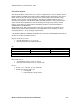
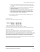
Document Number 050-015-008R05 Power Supply & Data Connectors Use a 12V/5A min. power supply to power up the Communicator 1000. Connect the red wire (Power) to +12V and the black wire (Ground) to GND. Connect the white wire (Ignition) to +12V to turn on the Communicator 100. Power Cable Serial Cable Fig 1 See Figure 1 for the cable connections and Figure 2 for the Power Cable details +12V GND Power Supply Cable Ignition +12V GND Ignition Red Black White Fig.
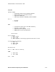
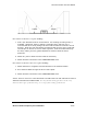
Document Number 050-015-008R05 GPS GSM A WLAN GSM B SIM Fig. 3 Fig.
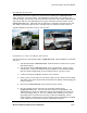
Document Number 050-015-008R05 Connection Procedure To operate and test this unit, a Power Supply Cable shown in fig.2 and a Serial Cable will be needed. A proper SIM card must be used with this device and prior to any use, the unit has to be activated on a cell network. The SIM card can be inserted on the front side of the Communicator 1000, by sliding the side plastic door upfront. Connect the Serial cable terminated with a DB9 connector to a PC.
Document Number 050-015-008R05 AT+CDV*22899 AT!STATUS Activate modem Get Modem status AT+CMIP? AT$QCMIP AT+CBIP? Mobile Station IP Address Query Mobile IP Behavior Get Base Station IP Address ATDT#777 Makes a data call Wireless Mmatrix Proprietary and Confidential 14/20
Document Number 050-015-008R05 System Verification List To verify the Wireless Matrix COMMUNICATOR 1000 System is operational; follow this checklist: 1. Verify the power source output is 9 to 36 volts. Check if the Power LED on the top of the unit is on. 2. Verify antenna connectivity. The LEDs for GPS, Cell and WLAN should be on. 3. Attempt to send a message to the host or have the host send a message to the vehicle.
Document Number 050-015-008R05 Warranty Wireless Matrix warrants that upon shipment to Customer from supplier’s facility and for the Warranty Period, hereinafter defined, the Equipment shall be free from defective materials and faulty workmanship and capable of accessing the Service ("Good Working Order").
Document Number 050-015-008R05 Return Policy If the troubleshooting process in the Potential Problems section of this guide determines the modem to be defective, return the unit to Wireless Matrix for repair. Contact your service provider and request a Return Material Authorization (RMA) number. To receive an RMA number, be prepared to provide: 1. Customer Address 2. Contact Name and Phone Number 3. Serial Number 4. P.O # (If unit is out of Warranty) 5.
Document Number 050-015-008R05 Wireless Mmatrix Proprietary and Confidential 18/20
Document Number 050-015-008R05 RMA form (continued) RMA Form BELOW IS FOR COMPLETION BY WIRELESS MATRIX Dead on Arrival In Warranty Replacement Unit(s) Transceiver Serial # Date Received Out of Warranty (please supply Purchase Order) Antenna Serial # Failure Type (Category & Code) Date Shipped Problem Description and Actions Taken (Factory use Only) Wireless Mmatrix Proprietary and Confidential Date/Tech Initials 19/20
Document Number 050-015-008R05 APPENDIX - Communicator 1000 Component List Wireless Matrix Communicator 1000 Component Name Part Number Wireless Matrix Communicator 1000 917-001-xxxx Power Cable 800-120-0243 Main Antenna QT10 Auxiliary Antenna FG-TC-21XLSMAMG4 Serial cable Required Components Cordless Drill Cable Connectors and Butt End Connector 5/16-inch and 1/2-inch Drill Bits Clear Silicone - Outdoor Sealant Socket Set Laptop (CSC) Recommended Tools & Supplies RS-232 Pin Extractor Wire Strip