
User's Manual


PAC Configuration Manual
Wireless Matrix Corporation #102, 1530 - 27 Avenue NE Page 59 of 62
Document # xxx-xxx-xxx Calgary, AB, Canada T2E 7S6
2002.02.01 Ph. 403.250.3949 Fax 403.250.8163 www.wrx-ca.com
6.2 TIN1
The terminal labeled TIN1 is designed for time measurements or discrete inputs. It can be
configured four different ways.
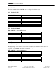
6.2.1 Digital (Off, On)
The digital input can be used for a 0-12 VDC input where 0 is OFF and a voltage above 2.5
volts is ON. This set up requires an external pull-down resistor if the input is not pulled low
by the end device. A 1/4 watt 10k ohm resistor is sufficient.
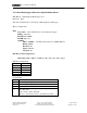
GDN ADD INT ? 9xx 1 0 0 0 0 discrete
PID ?
Point index 9xx
Address (channel number) 1
F1 0
F2 0
F3 0
F4 0
Point type discrete
6.2.2 Pulse Counter
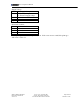
GDN ADD INT ? 9xx 1 2 0 255 6 uint
PID ?
Point index 9xx
Address (channel number) 1
F1 2 (Identifies pulse counter)
F2 0
F3
255 (Enable 2 kΩ pull-up resistor)
F4
6 (De-bounce interval of 24 µs (6 x 4µs))
Point type Uint