
User's Manual


PAC Configuration Manual
Wireless Matrix Corporation #102, 1530 - 27 Avenue NE Page 58 of 62
Document # xxx-xxx-xxx Calgary, AB, Canada T2E 7S6
2002.02.01 Ph. 403.250.3949 Fax 403.250.8163 www.wrx-ca.com
6.1 I/O1-I/O4
The four terminals labeled I/O1-I/O4 can be configured 3 different ways.
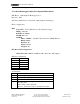
6.1.1 Analog (1-5V)
GDN ADD INT ? 9xx 1 0 0 0 0 float
PID ?
Point index 9xx
Address (channel number) 1 (1-4)
F1 0
F2 0
F3 0
F4 0
Point type Float
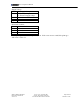
6.1.2 Analog (4-20mA)
GDN ADD INT ? 9xx 1 0 255 0 0 float
PID ?
Point index 9xx
Address (channel number) 1 (1-4)
F1 0 (Identifies analog input)
F2 255 (Enable current measurement)
F3 0
F4 0
Point type float
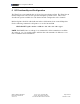
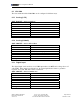
6.1.3 Digital input
The digital input can be used for a 0-12 VDC input where 0 is OFF and a voltage above 2.5
volts is ON. If the input is not driven low, an external pull-down resistor to ground is
required. A 1/4 watt 10k ohm resistor is sufficient.
GDN ADD INT ? 9xx 1 0 0 0 0 discrete
PID ?
Point index 9xx
Address (channel number) 1 (1-4)
F1 0
F2 0
F3 0
F4 0
Point type Discrete