
User's Manual

PAC Configuration Manual
Wireless Matrix Corporation #102, 1530 - 27 Avenue NE Page 40 of 62
Document # xxx-xxx-xxx Calgary, AB, Canada T2E 7S6
2002.02.01 Ph. 403.250.3949 Fax 403.250.8163 www.wrx-ca.com
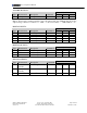
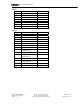
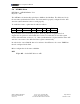
ANALOG OUTPUTS :
Channel Modifiers
Type Measurement Description Command
F2 F3 F4
32 Voltage Voltage VO - - Note 3
Note 3: F4 selects the channel variable to store the output value into. Without this, the analog
output voltage cannot be read back. i.e. (Addr = 7, F1=32, F4=200} = “ 7VO(=200CV) = x”
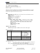
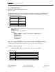
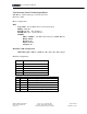
DIGITAL INPUTS:
Channel Modifiers
Type Measurement Description Command
F2 F3 F4
64 State 1 -Bit Input DS - - -
65 Nibble 4 -Bit Input DN - - -
66 Byte 8 -Bit Input DB - - -
67 Word 16 -Bit Input DW - - -
68 Counter 16 -Bit Up Counter C - - -
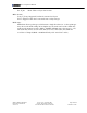
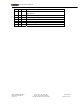
DIGITAL OUTPUTS :
Channel Modifiers
Type Measurement Description Command
F2 F3 F4
96 State 1 -Bit Output DSO - - -
97 Nibble 4 -Bit Output DNO - - -
98 Byte 8 -Bit Output DBO - - -
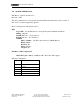
MISCELLANEOUS:
Channel Modifiers
Type Measurement Description Command
F2 F3 F4
255 Channel
Variable
Internal register CV - - -
254 System
Variable
Internal Maintenance SV - - -
253 System Timer Internal Timers ST - - -