
User's Manual

PAC Configuration Manual
Wireless Matrix Corporation #102, 1530 - 27 Avenue NE Page 39 of 62
Document # xxx-xxx-xxx Calgary, AB, Canada T2E 7S6
2002.02.01 Ph. 403.250.3949 Fax 403.250.8163 www.wrx-ca.com
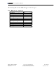
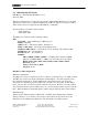
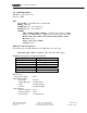
Channel Types
ANALOG INPUTS:
Channel Modifiers
Type Measurement Description Command
F2 F3 F4
0 Voltage no zero correction V - - Note 1
1 Voltage zero correction VNC - - Note 1
2 Current w/ external shunt I - - Note 1
3 Current 4-20mA current loop L - - Note 1
4 Resistance by 2,3,or 4 wire
method
R--Note 1
5 Conductivity by 2,3,or 4 wire
method
CO - - Note 1
6 Bridge 4-wire, quarter, half,
full
BGI - - Note 1
7 Radiometric 4&6 wire bridges BGV - - Note 1
8 Temperature Thermocouple T[c] Note
2a
-Note 1
9 Temperature Platinum RTD PT[n] Note
2b
-Note 1
10 Temperature Nickel RTD NI - - Note 1
11 Temperature Copper RTD CU - - Note 1
12 Temperature YS Series YS[n] Note
2b
-Note 1
13 Temperature AD Series AD[n] Note
2b
-Note 1
14 Temperature LM Series LM[n] Note
2b
-Note 1
15 Temperature TMP Series TMP[n] Note
2b
-Note 1
16 Temperature Diode Type DIODE - - Note 1
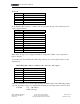
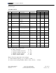
Note 1: F4 selects the channel usage
0 : Basic connection i.e.: 1V
1 : Positive terminal connection i.e.: 1+V
2 : Negative terminal connection i.e.: 1-V
3 : Default excitation applied i.e.: 1*V
4 : Return common terminal i.e.: 1#V
Note 2: F2 selects temperature sensor sub-type
2a : Selects Thermocouple type {1=A, 2=B, 3=C, 4=D,…}
2b : Selects sensor sub-type number {Addr=5, F1=12, F2=16 } = “5YS16”