
User's Manual

PAC Configuration Manual
Wireless Matrix Corporation #102, 1530 - 27 Avenue NE Page 23 of 62
Document # xxx-xxx-xxx Calgary, AB, Canada T2E 7S6
2002.02.01 Ph. 403.250.3949 Fax 403.250.8163 www.wrx-ca.com
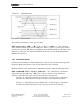
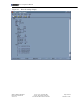
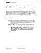
Figure 15: Alarm Hysterisis
“O” denotes a limit transition
The following command is used to enter an alarm.
GDN ALarm <index> <HH | *> <H | *> <L | *> <LL | *> <HYS | *> – This command
enters alarm thresholds for the specified I/O point. Enter * in place of a value if the alarm or
hysterisis not specified. HH denotes the high-high alarm threshold, H denotes the high alarm
threshold, L denotes the low alarm threshold, LL denotes the low-low alarm threshold and
HYS denotes hysterisis.
3.4.1 Deadband Alarms
A dead-band alarm monitors a single I/O point for a change that is greater then the specified
threshold. Dead-band alarms are not relevant when low-power is enabled.
Dead-band alarms can be added via the command line interface using the following format.
GDN ALARM DB <index> <Npoints> <DB Value> – The command sets a dead-band
alarm for the specified I/O point. <DB Value> is the dead-band or change threshold.
<Npoints> determines the mode of the dead band alarm as shown below:
Npoints = 0 – Dead-band from last reported value. An alarm report is sent when a
new I/O value differs from the last reported value by more then the dead-band.
Npoints = 1 – Dead-band from last sampled value. An alarm report is sent when a
new I/O value differs from the previous value by more then the dead-band.