
User's Manual

PAC Configuration Manual
Wireless Matrix Corporation #102, 1530 - 27 Avenue NE Page 22 of 62
Document # xxx-xxx-xxx Calgary, AB, Canada T2E 7S6
2002.02.01 Ph. 403.250.3949 Fax 403.250.8163 www.wrx-ca.com
The index is a unique number that identifies the I/O point within the PAC. If a new I/O point
is added with the same index as an existing I/O point, the new point will overwrite the
existing point. Valid index numbers are 1-127 and 256-1200 (128-255 are reserved for PAC
internal I/O points).
The following commands are used to create and modify the I/O list. The I/O list is set up
differently for each RTU Driver. See the RTU driver section for the appropriate setup. The
commands for configuring I/O points are:
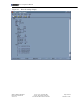
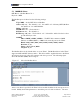
GDN LIst <pid> – This command will list the I/O points in the poll-set. Valid values for
<pid> are 1-255. Type "GDN LIST 255" to display the internal I/O points. Type "GDN
LIST" without a number to list all the I/O points except PAC internal I/O points (PID 255).
GDN ADd <pid><index><address><f1><f2><f3><f4><type> – Use this command to add
or modify an I/O point. Specify a unique index to add a point. Specify the index of an
existing point to modify the point. Refer to the appropriate RTU driver section for a
definition of the <address>, <f1>, <f2>, <f3> and <f4> parameters. The <type> parameter
can be one of the following: 1=discrete 2=char 3=uchar 4=int 5=uint 6=long 7=ulong 8=float
GDN REad <index> – Read the current value of the specified I/O point.
GDN WRite <index> <value> – Write a new value to the specified I/O point.
GDN DElete <index> – Erase the specified I/O point from the PAC.
3.4 Alarms
An alarm is a threshold value specific to an I/O point. The alarm values are stored in the
PAC. If the PAC reads the value of an I/O point and determines the value has crossed the
threshold, the PAC will send an alarm-report. The alarm-report contains the values of all the
I/O points in the poll-set. The PAC sends an alarm report when the value crosses into the
alarm region and another report when the value crosses out of the alarm region. Alarms are
normally added remotely through IP Anywhere when a site is commissioned.
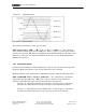
Each I/O point can have 4 alarm thresholds High-High, High, Low, Low-Low and a
hysterisis. Hysterisis changes the alarm threshold for an I/O point to cross out of the alarm
region. The threshold is modified by the value of the hysterisis. Hysterisis is used to prevent
excessive alarm reports from an I/O value that is close to the threshold and is bouncing back
and forth across the threshold.
Example: A high alarm is set to 10 and the hysterisis is set to 2. If the measured value rises to
11, an alarm will occur and an alarm report is sent. The I/O point will not return to normal
until the value drops below 8. If the value drops from 11 to 9 and then returns to 11, the I/O
point stays in alarm condition and an alarm report not sent.