
User's Manual

PAC Configuration Manual
Wireless Matrix Corporation #102, 1530 - 27 Avenue NE Page 11 of 62
Document # xxx-xxx-xxx Calgary, AB, Canada T2E 7S6
2002.02.01 Ph. 403.250.3949 Fax 403.250.8163 www.wrx-ca.com
2.1 Installation Considerations
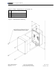
Mounting:
• The TPAC has mounting holes beneath the cover of the enclosure. The mounting
holes are spaced 93 x 180 mm. The mounting holes are 7.5 mm in diameter and the
access holes are 11 mm in diameter. The TPAC can be mounted to a panel using
appropriate screws for the panel material.
• The TPAC should be mounted with the antenna vertical on the top of the enclosure.
The conduit entry/cable seal should point down.
• Ensure end devices are within an acceptable distance from the TPAC.
Power:
• The TPAC requires 9-28 VDC to operate. Maximum current draw is 1 A.
• Power is applied at the Vin and GND terminals.
• The metal case of the TPAC must be grounded at one of the mounting holes.
• The TPAC can put itself into a sleep mode to conserve power. The minimum duty
cycle is 30 seconds per day. Current draw in sleep mode is under 1 mA.
Terrestrial network:
• Prior to installing a TPAC with a DataTAC communication module, check the
Motient or Bell Mobility coverage map to ensure the site is in range of the network.
• If the site is near the edge of coverage, a site survey may be necessary to verify
coverage and determine the optimal place to install the TPAC.
• Install the TPAC so there are minimal obstructions between the TPAC and the nearest
network tower. Network towers are concentrated in urban centers.
• There is a small green LED at the top of the TPAC printed circuit board. The LED
will illuminate when the TPAC is in coverage of the network. The TPAC must be
commissioned before the LED will function.
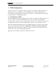
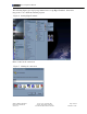
• The TPAC displays network signal strength on the configuration port when it boots.
Other Wiring:
• The serial connection to the end device is made using the terminal blocks for COM2
(RS232) or COM4 (RS485).
• The terminal WK LN can be shorted to ground to manually wake the TPAC from
sleep mode.
• The terminal +V EXT can be used to supply power to an external device. The
voltage is the same as supplied to +V IN. Current is limited to 200 mA. The TPAC
controls whether power is available at the terminal.
• The terminal DI/O can be used as a digital input or output.
• Analog inputs (4-20 mA or 1-5 V) can be wired into the terminals labeled I/O1 to
I/O4. Digital inputs can be wired into the I/O terminals too.
• The terminal TIN1 can be used as a pulse counter, frequency counter or digital input.
• Refer to the wiring diagram that is specific to the application.