Terrestrial Processor Assisted Connector Installation and Configuration Manual Version 2.2X W ireless Matrix Corporation Document # xxx-xxx-xxx 2002.02.01 #102, 1530 - 27 Avenue NE Calgary, AB, Canada T2E 7S6 Ph. 403.250.3949 Fax 403.250.8163 Page 1 of 62 www.wrx-ca.
TPAC Configuration Manual IP Anywhere TPAC Configuration Manual Copyright © 2002 Wireless Matrix. All rights reserved. Printed in Canada This document is proprietary to Wireless Matrix Corporation. Do not reproduce, use or disclose without permission. We have made every effort to ensure the accuracy of all information contained in this document.
FCC RF EXPOSURE INFORMATION Please read this information before use In August 1996 the Federal Communications Commission (FCC) of the United States with its action in Report and Order FCC 96 -326 adopted an updated safety standard for human exposure to radio frequency (RF) electromagnet ic energy emitted by FCC regulated transmitters. Those guidelines are consistent with the safety standard previously set by both U.S. and international standards bodies.
TPAC Configuration Manual Table of Contents ABOUT THIS MANUAL ...................................................................................................6 CONVENTIONS.................................................................................................................7 1 INTRODUCTION ........................................................................................................8 1.1 2 TPAC SPECIFICATIONS ........................................................................
TPAC Configuration Manual 6.1 I/O1-I/O4 ...............................................................................................................58 6.1.1 Analog (1-5V) .................................................................................................58 6.1.2 Analog (4-20mA).............................................................................................58 6.1.3 Digital input.....................................................................................................
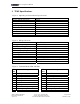
PAC Configuration Manual List of Figures Figure 1: Operating and environmental specifications ..........................................................9 Figure 2: RF Specifications ..................................................................................................9 Figure 3: Terminal Blocks (TB1 and TB2) ...........................................................................9 Figure 4: TPAC configuration port (3-pin header: J4)........................................................
PAC Configuration Manual About This Manual The Terrestrial Processor Assisted Connector (TPAC) Installation and Configuration Manual will assist the user to understand the fundamentals of TPAC configuration and operation. The manual assumes that the user has basic knowledge of serial communication, end devices and electrical installation and wiring. W ireless Matrix Corporation Document # xxx-xxx-xxx 2002.02.01 #102, 1530 - 27 Avenue NE Calgary, AB, Canada T2E 7S6 Ph. 403.250.3949 Fax 403.250.
PAC Configuration Manual Conventions The Terrestrial Processor Assisted Connector will be referred to as the TPAC from this point forward. TPAC configuration commands are displayed in bold type followed by < >. The < > brackets indicate a variable should be entered. Example: GDN ADd The TPAC interface uses minimum truncation. This means that only the letters that are capitalized need to be entered when programming the TPAC. The TPAC is not case sensitive.
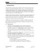
PAC Configuration Manual 1 INTRODUCTION The terrestrial processor assisted connector (TPAC) is a device that is an interface between an end-device and the Wireless Matrix IP Anywhere service. A terrestrial communications medium is an integral part of the TPAC. The term “terrestrial” is used to differentiate the communication network from a “space” (satellite) network.
PAC Configuration Manual 2 TPAC Specifications Figure 1: Operating and environmental specifications Input voltage Receive current (Vin=12V) Transmit current (Vin=12V) Sleep mode current (Vin=12V) Operating temperature Vibration Serial ports Dimensions Mounting holes Weight 9-28 VDC 80 mA 1A 1 mA -30 to 70 °C TBD 3 (2xRS232 + 1xRS485) 200 x 140 x 90 mm (7.9 x 5.5 x 3.5”) 180 x 93 mm (7.1 x 3.7”) 2 kg (4.25 lbs.
PAC Configuration Manual Figure 4: TPAC configuration port (3-pin header: J4) J4 Pin 1 2 3 Description COM2T: RS232 transmit COM2R: RS232 receive GND: ground Figure 5: TPAC Mechanical Drawing W ireless Matrix Corporation Document # xxx-xxx-xxx 2002.02.01 #102, 1530 - 27 Avenue NE Calgary, AB, Canada T2E 7S6 Ph. 403.250.3949 Fax 403.250.8163 Page 10 of 62 www.wrx-ca.
PAC Configuration Manual 2.1 Installation Considerations Mounting: • The TPAC has mounting holes beneath the cover of the enclosure. The mounting holes are spaced 93 x 180 mm. The mounting holes are 7.5 mm in diameter and the access holes are 11 mm in diameter. The TPAC can be mounted to a panel using appropriate screws for the panel material. • The TPAC should be mounted with the antenna vertical on the top of the enclosure. The conduit entry/cable seal should point down.
PAC Configuration Manual 3 TPAC Configuration The TPAC needs to be configured to function properly. The TPAC is shipped with factory default settings. The configuration can be modified via the communication network or locally using a programming cable from a PC to the TPAC. A site information sheet should be prepared prior to configuring the TPAC. 3.1 Interfacing to a TPAC A Wireless Matrix TPAC programming cable is required to configure the TPAC using a local PC.
PAC Configuration Manual The following figures give step by step instructions to set up HyperTerminal. Some users may prefer to use a different terminal program. Figure 6: Starting HyperTerminal Enter a name for the connection. Figure 7: Naming the connection W ireless Matrix Corporation Document # xxx-xxx-xxx 2002.02.01 #102, 1530 - 27 Avenue NE Calgary, AB, Canada T2E 7S6 Ph. 403.250.3949 Fax 403.250.8163 Page 13 of 62 www.wrx-ca.
PAC Configuration Manual Select the COM port for the serial port connected to the TPAC. Figure 8: Choose a COM port Specify the communication settings, as shown below. Figure 9: Specify port settings Click the OK button. Then click on the Call Disconnect and then Call Connect buttons. (New port settings do not take effect until the session has been disconnected and reconnected.) Hit and the PAC> prompt should appear. . The TPAC is ready for configuration.
PAC Configuration Manual Save the settings so the session is available in the future. The session is saved using the File|Save menu option. The settings for the session can be viewed or changed using the File|Properties menu option. Figure 7: PAC prompt If the prompt PAC> does not appear on the screen, the TPAC may be in sleep mode. Try cycling the power or shorting the WK LN terminal to the GND terminal to wake the TPAC. W ireless Matrix Corporation Document # xxx-xxx-xxx 2002.02.
PAC Configuration Manual 3.2 TPAC User Interface This section assumes the programmer has the basic understanding of the TPAC functionality and the end devices connected to the TPAC. The TPAC is configured using the PAC command line interface. The PAC command line interface has a tree structure and uses minimum truncation so only letters necessary to make the command unique need to be entered. The manual shows the necessary characters in capital letters. The PAC command line interface is not case sensitive.
PAC Configuration Manual Figure 10: Display the version 3.2.2 Setting PAC Values The “SHow” command displays all the PAC settings. The settings are displayed as a tree of main settings with sub settings. To set a specific value, the complete path to the setting must be given. For example, to set the RTU’s baudrate, issue the command… RTU COMM BAUD 3.2.3 Loading Drivers The default RTU driver in the PAC is Modbus.
PAC Configuration Manual Figure 11: Load new RTU drivers Type VER to list all drivers. Type RTU TYPE to list the RTU drivers. Type NET TYPE to list the network drivers. The PAC must be Halted before changing a driver. See the following figures for examples. Figure 12: RTU Types W ireless Matrix Corporation Document # xxx-xxx-xxx 2002.02.01 #102, 1530 - 27 Avenue NE Calgary, AB, Canada T2E 7S6 Ph. 403.250.3949 Fax 403.250.8163 Page 18 of 62 www.wrx-ca.
PAC Configuration Manual Figure 13: Network Types Ensure that the proper drivers are loaded before continuing with the configuration. 3.2.4 Displaying and Setting the System Time Time is tracked in GMT in the PAC. The PAC can display or set time in the local time, if an offset from GMT is defined. Define the time zone offset before setting the time. Time values are set as follows: TIme or DAte – Display the current local time or date.
PAC Configuration Manual Figure 14: Setting the system time 3.2.5 PAC Application Commands The default values in the PAC configuration are usually acceptable. The following list of commands is used to configure the PAC global settings. Note: The parameters inside the brackets < > must be entered. The symbol “|” is “or” so on | off indicates “on” or “off” is entered. PAC RPTBack – Report-back causes the PAC to send an acknowledgement back to the GDN that a message was received successfully.
PAC Configuration Manual PAC ARChive – This setting is for Wireless Matrix configuration only. The default is ON and it should be left ON. PAC POW <0…> – Pause on wake-up. This setting delays the PAC from polling for a set amount of time in seconds. This is used to provide transmitters time to stabilize when using the PAC on-board I/O. This setting is also used when the communication device needs a delay to "key up" after receiving DTR.
PAC Configuration Manual The index is a unique number that identifies the I/O point within the PAC. If a new I/O point is added with the same index as an existing I/O point, the new point will overwrite the existing point. Valid index numbers are 1-127 and 256-1200 (128-255 are reserved for PAC internal I/O points). The following commands are used to create and modify the I/O list. The I/O list is set up differently for each RTU Driver. See the RTU driver section for the appropriate setup.
PAC Configuration Manual Figure 15: Alarm Hysterisis “O” denotes a limit transition The following command is used to enter an alarm. GDN ALarm – This command enters alarm thresholds for the specified I/O point. Enter * in place of a value if the alarm or hysterisis not specified.
PAC Configuration Manual Npoints > 1 – Dead-band from average value. An alarm report is sent when a new I/O value differs from the average of the previous values by more then the dead-band. Disable a dead-band alarm by setting the alarm dead-band value to zero. 3.5 Scheduling Scheduling is one of the most important features of the PAC. Two important scheduling concepts are start time and interval time. Start Time - This is the date and time the PAC will start the event.
PAC Configuration Manual Interval HH:MM:SS – Default start date = 01/01/80 HH:MM – Default start date = 01/01/80; Default second = 00. Time between events. Long format: DD HH:MM:SS Where DD = days (00-99) Brief format. HH:MM:SS – Default days = 00 HH:MM – Default days = 00, Default seconds = 00. EVENT DELETE – This command disables an event. EVENT LIST – This command displays all active events. Note: Short forms can be used to modify existing events.
PAC Configuration Manual 4 TPAC Network Drivers and Settings The TPAC network driver is type “RIM”. Display the network settings by typing “SHOW NET”. This section contains detailed information to configure the network driver. NET TYpe RIM – Type "NET TYPE" to list all the available drivers in the PAC. Only the “RIM” network driver is relevant to the TPAC. DEbug – Turn on this level of debug to view network-level application messages. The messages can help with troubleshooting.
PAC Configuration Manual Figure 16: Network settings display W ireless Matrix Corporation Document # xxx-xxx-xxx 2002.02.01 #102, 1530 - 27 Avenue NE Calgary, AB, Canada T2E 7S6 Ph. 403.250.3949 Fax 403.250.8163 Page 27 of 62 www.wrx-ca.
PAC Configuration Manual 5 TPAC RTU Drivers and Settings The RTU driver is one of the first parameters that should be set when configuring a TPAC. Select the appropriate driver for the application. The TPAC is capable of polling many different devices. Some of the most common TPAC RTU drivers are Modbus (RTU, ASCII, Daniel, Modicon and Enron), ROC Protocol and Allen Bradley DF1. New drivers are added frequently. The different drivers do not have all the same configuration parameters.
PAC Configuration Manual 5.1 MODBUS Driver RTU Driver : Modbus Driver V1.2 KeyCode : MBP The Modbus protocol driver has the following settings: RTU TYpe MBP – Set the RTU driver to Modbus. ASCii – The default is “off”. Set ASCII “off” for binary (RTU) Modbus. Set ASCII “on” for ASCII Modbus. DEbug MAXRetries <2> – The default is 2. RXTimeout <2> – The default is 2. BYTEswap – The default is “off”. It should be enabled for devices that provide Intel byte order.
PAC Configuration Manual figure shows an example of a TPAC configuration for Modbus ASCII, 9600 baud, 7 data bits, and even parity. Figure 18: Configure TPAC for Modbus ASCII Check the parameters by typing “SHow”. Figure 19: Check Settings for Modbus ASCII Verify the settings are correct and type “ WRite” to save the settings to non-volatile memory. The next figure is an example of a TPAC configuration for Modbus RTU, 9600 baud, 8 data bits, and even parity.
PAC Configuration Manual Check the parameters by typing “SHow”. Figure 21: Check Settings for Modbus RTU Verify the settings are correct and type “ WRite” to save the settings to non-volatile memory. MBP Driver I/O Configuration I/O points for Modbus are determined by the Modbus register number and type. Add or modify and I/O point to the TPAC with the following command and the parameters. GDN ADd TPAC I/O point definition for the Modbus driver.
PAC Configuration Manual 5.2 ROC Protocol Driver RTU Driver : ROC Driver V1.2 KeyCode : ROC The ROC protocol driver has the following settings: RTU TYpe ROC – Set the RTU driver to ROC protocol. DEbug MAXRetries <3> – The default is 3. RXTimeout <2> – The default is 2. Unit <240> – This is the unit number of the PAC. The default is 240. Group <240> – This is the group number of the PAC. The default is 240. COMM POrt – The RTU driver must use COM2 (RS232) or COM4 (RS485).
PAC Configuration Manual Most ROC devices have default communication settings of 9600 bits per second, 8 data bits, no parity and 1 stop bit. If the communication is not working, use ROCLINK of GV101 to verify the ROC settings. The next figure shows a sample ROC configuration. Figure 23: ROC Configuration ROC Driver I/O Configuration Add or modify and I/O point to the TPAC with the following command and the parameters.
PAC Configuration Manual The following table correlates ROC data types to PAC data types. PAC - ROC data type comparison PAC data types 1 – Discrete 2 – Char 3 – Unsigned char 4 – Integer 5 – Unsigned integer 6 – LONG 7 – Unsigned long 8 – Float Not supported Not supported Not supported W ireless Matrix Corporation Document # xxx-xxx-xxx 2002.02.01 ROC Data Type UC SC UC SI UI SL UL FL AC BN TLP #102, 1530 - 27 Avenue NE Calgary, AB, Canada T2E 7S6 Ph. 403.250.3949 Fax 403.250.8163 Page 34 of 62 www.
PAC Configuration Manual 5.3 Allen Bradley DF1 Driver RTU Driver : Allen Bradley DF1 Driver V2.1 KeyCode :DF1 This driver will interface to a PLC that supports the Allen Bradley DF1 Protocol. The PAC implements a subset of the commands transported via DF1 so support is restricted to PLCs which use the “Protected Typed Logical Read/Write” commands.
PAC Configuration Manual TN:E.S/B Component T N E S B Description File Type File number Element number Sub-element number Bit number In all Allan Bradley references, a letter or letters specify the file type.
PAC Configuration Manual Example: DF1 Address F8:4 N7:3 N7:3/4 W ireless Matrix Corporation Document # xxx-xxx-xxx 2002.02.01 F1 138 137 04137 F2 8 7 7 F3 4 3 3 F4 0 0 0 Type Float Int Disc #102, 1530 - 27 Avenue NE Calgary, AB, Canada T2E 7S6 Ph. 403.250.3949 Fax 403.250.8163 Page 37 of 62 www.wrx-ca.
PAC Configuration Manual 5.4 DataTaker Driver RTU Driver : Data Taker V1.2 KeyCode : DTK RTU TYpe DTK – Set the RTU driver to DataTaker. DEbug MAXRetries <2> – The default is 2. RXTimeout <1> – The default is 1. COMM POrt – The RTU driver must use COM2 (RS232) or COM4 (RS485). COM1 is the network port for the TPAC.
PAC Configuration Manual Channel Types ANALOG INPUTS: Command V VNC I L R Channel Modifiers F2 F3 F4 Note 1 Note 1 Note 1 Note 1 Note 1 CO - - Note 1 BGI - - Note 1 Radiometric Temperature Description no zero correction zero correction w/ external shunt 4-20mA current loop by 2,3,or 4 wire method by 2,3,or 4 wire method 4-wire, quarter, half, full 4&6 wire bridges Thermocouple BGV T[c] - Note 1 Note 1 9 Temperature Platinum RTD PT[n] - Note 1 10 11 12 Temperature Temperature Temperatu
PAC Configuration Manual ANALOG OUTPUTS : Type Measurement 32 Voltage Description Voltage Command VO Channel Modifiers F2 F3 F4 Note 3 Note 3: F4 selects the channel variable to store the output value into. Without this, the analog output voltage cannot be read back. i.e.
PAC Configuration Manual 5.5 Toshiba Tosvert-130 Driver RTU Driver : Toshiba Tosvert-130 Driver V1.0 KeyCode : TOS This driver controls the Toshiba Tosvert-130 Transistor inverter. While there are various models in the Tosvert-130 product line, the driver was designed for the G3 series. Other models may be supported, but have not been tested. RTU TYpe TOS – Set the RTU driver to the Toshiba Tosvert-130 Transistor inverter. DEbug CHKsum – The default is on.
PAC Configuration Manual Int, U_Int: Read / Write a 2-byte data location Other formats: Long, U_Long: Supported, but data is truncated to 2-bytes Float : Supported. but data is converted from a 2-byte integer. Mask usage: Other than discrete point types, which return a single bit value 0 or 1, other point type may also use the mask setting. In its simplest use, the mask can be used to limit data written to the memory location.
PAC Configuration Manual 5.6 Spartek SS6010 Driver RTU Driver : Spartek Systems V1.2 KeyCode : SPR This driver will interface to the Spartek Systems SS6010 and 6010A down-hole recorder as laid out in a document supplied by Spartek. Driver Configuration (with default values): RTU TYpe SPR – Set the RTU driver to the Spartek Systems SS6010 and 6010A. DEbug MAXRetries <2> – The default is 2. RXTimeout <2> – The default is 2. COMM POrt < COM2> – The RTU driver must use COM2 (RS232).
PAC Configuration Manual SS6010 F1 0 1 2 3 4 5 6 7 SS6010a F1 0 1 2 3 4 5 6 7 8 9 10 11 12 13 14 Point Description Serial Number Elapsed time in secs Pressure Temperature Tool Configuration Raw pressure Raw temperature Tool Status Point Type Unsigned Long Unsigned Long Float Float Unsigned Long Unsigned Long Unsigned Long Unsigned Long Point Description Serial # Time Date Rawdata1 Rawdata2 Rawdata3 Rawdata4 Computed Pressure 1 Computed Temperature 1 Computed Pressure 2 Computed Temperature 2 Computed Pr
PAC Configuration Manual 5.7 Garmin GPS Driver RTU Driver : Garmin GPS 25/35 Driver V2.0 KeyCode : GPS The Garmin GPS driver uses the "Phase Output Data Binary Format" for its communications with the RTU. As the binary format messages are transmitted on TXD2/RXD2, the cables must be connected as follows PAC GPS RS232-RX Pin TXD2 2 (Purple) RS232-TX Pin RXD2 3 (Green) Vdc Vin (Red) GND GND (Black) RTU TYpe SPR – Set the RTU driver to the Spartek Systems SS6010 and 6010A.
PAC Configuration Manual F1 40 F2 0 Type UInt 40 40 40 40 40 40 1 2 3 4 5 6 FL FL FL FL FL FL W ireless Matrix Corporation Document # xxx-xxx-xxx 2002.02.01 GPS Fix (0=Invalid, 1=Invalid, 2=2D, 3=3D, ...) (see appendix C) GPS Latitude (deg) (+ == North, - == South) GPS Longitude (deg) (+ == East, - == West) GPS Altitude (mt) Velocity : Latitude (mt/sec) Velocity Longitude (mt/sec) Velocity : Altitude (mt/sec) #102, 1530 - 27 Avenue NE Calgary, AB, Canada T2E 7S6 Ph. 403.250.3949 Fax 403.250.
PAC Configuration Manual 5.8 Delimited ASCII Driver RTU Driver : Delimited ASCII Driver V1.0 KeyCode : DAD The DAD driver is designed to receive an ASCII delimited string. The driver does not send queries to the end device. The driver is designed to receive data only. The Driver can be set up to accept all type of delimitation. Commas and spaces are usually the most common. Also the number of expected values can be entered to filter invalid data.
PAC Configuration Manual 5.9 AFI MVS Driver RTU Driver : AFI MVS Driver V1.1 KeyCode : AFI The AFI Driver is functionally equivalent to Modbus (See Modbus). The difference lies in the auto-time synchronization feature. Two items must be properly configured for the AFI auto-time synchronization feature to work properly. To enable the feature, a point must be added as follows.
PAC Configuration Manual 5.10 Pressure Trax ILI Technologies Driver RTU Driver : ILI Technologies : PressureTrax V1.1 KeyCode : PRT Driver configuration: RTU TYpe PRT – Set the RTU driver to the PressureTrax. DEbug RXTimeout <8> – The default is 5. MAXRetries <2> – The default is 2. COMM POrt < COM2> – The RTU driver must use COM2 (RS232).
PAC Configuration Manual 5.11 ABB PowerPlus Alpha Driver RTU Driver : ABB PowerPlus Alpha Driver V1.0 KeyCode : ABB Driver configuration: RTU TYpe ABB – Set the RTU driver to the ABB. DEbug RXTimeout <1> – The default is 1. MAXRetries <8> – The default is 8. PWord <0> – The default is 0. BM – The default is off. COMM POrt < COM2> – The RTU driver must use COM2 (RS232).
PAC Configuration Manual 5.12 Environmental Systems Corporation (ESC) Data Logger Driver RTU Driver : Environmental Systems Data Logger 8816 V1.0 KeyCode : ESC The driver was tested with the Model 8816 Data Logger Driver configuration: RTU TYpe ESC – Set the RTU driver to the ESC data logger. DEbug MAXRetries <2> – The default is 2. COMM POrt < COM2> – The RTU driver must use COM2 (RS232).
PAC Configuration Manual F4 TYPE 0:Relative offset, 1:Absolute time INT F1 F2 TYPE 23 Poll Digital Input Status Line number DISCRETE F1 F2 F3 TYPE 45 Poll Calibration results Channel # Phase (0:"ZERO", 1:"SPAN") FLOAT F1 F2 F3 F4 TYPE 54 Poll Auxiliary Averages Channel # Hour/Min 0:Relative offset, 1:Absolute time FLOAT F1 F2 F3 F4 TYPE 55 Poll Auxiliary Averages Channel # Hour/Min 0:Relative offset, 1:Absolute time INT F1 F2 F3 TYPE 56 : Poll Averages Channel # Interval (minutes) FLOAT F1 F2 T
PAC Configuration Manual F2 TYPE Channel # FLOAT F1 TYPE 1212 Get current RTU time ULONG F1 F2 TYPE 1516 Switch digital output control relay Line number DISCRETE Note : This is a write-only point. The PAC will maintain the last value sent as long as power is maintained. Sleep or any power loss will invalidate this point, and a default value of OFF is returned. W ireless Matrix Corporation Document # xxx-xxx-xxx 2002.02.01 #102, 1530 - 27 Avenue NE Calgary, AB, Canada T2E 7S6 Ph. 403.250.
PAC Configuration Manual 5.13 Grant DataLogger 1000 series Squirrel Meter Driver RTU Driver : 1000 Squirrels Datalogger V1.0 KeyCode : 1KS This driver will interface to the Grant “1000 Squirrels” Datalogger. Driver configuration: RTU TYpe 1KS – Set the RTU driver to the Grant data logger. DEbug RXTimeout <2000> MAXRetries <2> COMM POrt < COM2> – The RTU driver must use COM2 (RS232).
PAC Configuration Manual Supply Voltage F1 86 – Supply Voltage F2 1 = Battery voltage 2 = External supply voltage F3 not used. F4 not used. Type Float Reset Pulse Counter F1 83 - Reset Pulse counter F2 not used. F3 not used. F4 not used. Type Discrete. Reading this point will reset the pulse counters. If the reset was successful, this point type will return a value of 1 W ireless Matrix Corporation Document # xxx-xxx-xxx 2002.02.01 #102, 1530 - 27 Avenue NE Calgary, AB, Canada T2E 7S6 Ph. 403.250.
PAC Configuration Manual 5.14 Bristol Babcock BSA Driver RTU Driver : Bristol Babcock Protocol V1.0 KeyCode : BSA This driver controls the Toshiba Tosvert-130 Transistor inverter. While there are various models in the Tosvert-130 product line, the driver was designed for the G3 series. Other models may be supported, but have not been tested. Configuration of the driver is as follows.
PAC Configuration Manual 6 I/O Functionality and Configuration The TPAC has seven terminals that can be used for general-purpose I/O. The TPAC has an internal temperature sensor and an optional atmospheric pressure sensor. This section describes the options available for each channel and the configuration of the channels. I/O board points should be added with 9xx index to differentiate from external I/O points. Use the following command to add points to access the internal I/O.
PAC Configuration Manual 6.1 I/O1-I/O4 The four terminals labeled I/O1-I/O4 can be configured 3 different ways. 6.1.1 Analog (1-5V) GDN ADD INT ? 9xx 1 0 0 0 0 float PID ? Point index 9xx Address (channel number) 1 (1-4) F1 0 F2 0 F3 0 F4 0 Point type Float 6.1.2 Analog (4-20mA) GDN ADD INT ? 9xx 1 0 255 0 0 float PID ? Point index 9xx Address (channel number) 1 (1-4) F1 0 (Identifies analog input) F2 255 (Enable current measurement) F3 0 F4 0 Point type float 6.1.
PAC Configuration Manual 6.2 TIN1 The terminal labeled TIN1 is designed for time measurements or discrete inputs. It can be configured four different ways. 6.2.1 Digital (Off, On) The digital input can be used for a 0-12 VDC input where 0 is OFF and a voltage above 2.5 volts is ON. This set up requires an external pull-down resistor if the input is not pulled low by the end device. A 1/4 watt 10k ohm resistor is sufficient.
PAC Configuration Manual 6.2.3 RPM meter GDN ADD INT ? 9xx 1 3 5 255 6 float PID ? Point index 9xx Address (channel number) 1 F1 3 (Identifies RPM meter) F2 5 (Sampling interval: 0 instantaneous value, 1 and greater indicates the sample rate. For example, 5 indicates a calculation every 5 seconds.) F3 255 (Enable 2 kΩ pull-up resistor) F4 6 (De-bounce interval of 24 µs (6 x 4µs)) Point type Float 6.2.
PAC Configuration Manual 6.3 Temperature and Pressure The temperature in °C is available on the TPAC. The atmospheric pressure in kPa is an option on the TPAC. 6.3.1 Temperature in °C GDN ADD INT ? 9xx 7 0 0 0 0 float PID ? Point index 9xx Address (channel number) 7 (Identifies temperature measurement) F1 0 F2 0 F3 0 F4 0 Point type float 6.3.
PAC Configuration Manual Appendix A Text file configuration. A text file can be created to simplify configuration if multiple units will have the same configuration. Create a text file using notepad or another text editor. Within the text file, enter the commands to configure the PAC followed by the key. Use a terminal program transfer or send the text file to the TPAC. In HyperTerminal, this option is found under the menu heading “Transfer | Send Text File”.