WINEGARD ® Movin’ View TM Digital Satellite Mobile Antenna for Two Receivers for Use While Stationary or In-Motion Model MV-4002 Made in the U.S.A. U.S. Patent Nos. 6,023,247; 6,188,300 Winegard Company • 3000 Kirkwood St. • Burlington, IA 52601-2000 319/754-0600 • FAX 319/754-0787 • www.winegard.com Printed in U.S.A. © Winegard Company 2005 2452062 Rev.
Introduction/How Does Digital Satellite TV Work? About this manual —We hope this manual will provide clear instructions to install and operate MV-4002. Two symbols have been used — Indicates suggestions to make Indicates caution should be taken! processes easier for you. ! Introduction Congratulations! You have purchased one of Winegard’s latest developments in the mobile satellite reception product line —the Movin’ ViewTM.
Quick Reference Guide NOTICE! This model is PRESET for DIRECTV® receivers. If you have a DISH Network® or ExpressVu® (Canada) receiver, you must change the numbered switches inside the dome. TO CHANGE SWITCHES INSIDE DOME — 1. Remove screws holding dome to base and remove dome. Place dome in safe spot to avoid damage. Switches will be set at 101° for DIRECTV®. You will be changing these switches.
Operation b. If it moves off the signal , it is in an effort to verify the signal and it should return to the signal shortly. 1. Turn on receiver and television set. The MV-4002 must be connected to a receiver that is plugged into 120 VAC. 5. After the unit has verified that it has the correct satellite, it will continue to fine tune for about 6 minutes (unless the vehicle is in-motion, see 7 below). 2. Verify that you are getting the receiver’s menu screens on the television.
To toggle between satellites when subscribing to multi-satellite programming— While in Sleep Mode, the MV-4002 will toggle between the primary and seconday satellites for either DISH Network or DIRECTV. Both have programming on more than one satelite.When a channel is selected on the remote control and is not on the satellite currently selected, the unit will automatically move to the correct satellite.
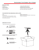
Parts Included • Tools Needed • How to Unpack PARTS INCLUDED: 1 Radome 1 Power switch 1 Wall plate (white) 1 Surface mount box 1 Cable entry plate 1 large yellow spade connector 2 small red spade connectors All required screws and washers 1 base with electronics, dish, single LNBF 30’ power cable and 30’ coaxial cable TOOLS NEEDED FOR UNPACKING & INSTALLATION: Level Drill w/3/4” bit 1-1/4” hole saw (if mounting switch in wall) 3/8” Box/Open end wrench for dome screws 7/16” Open end wrench Phillips screw
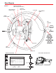
Base Diagram SWITCH LOCATION FIGURE 2 (SIDE OF BOX, SEE PAGE 3) CONTROL BOX TO LNBF COAX CABLE AT CONTROL BOX EL MOTOR GPS ANTENNA CABLE +12VDC POWER CABLE GPS ANTENNA CONTROL CENTER LINE OF THE VEHICLE BOX (DETAIL BELOW) AZ MOTOR FOOT MUST BE PARALLEL TO THE CENTER LINE OF THE VEHICLE LNBF VOLTAGE REFLECTOR CONTROL BOX DETAIL ELECTRONICS INTERIOR VIEW Vehicle Front A Mount Option A Vehicle Front B Mount Option B (#1 represents Switch DOWN; #0 represents Swi
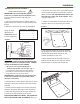
Installation Installing unit on roof of vehicle — Install in DRY conditions only! ! 6. Place the unit on the roof in its permanent location and mark around the base bracket, Figure 4. (Make sure the rear adjustable base foot is parallel with the center line of the vehicle. Refer to page 3, Figure 1A ). IMPORTANT! Do not install this system in the rain, or under any wet conditions. Moisture may affect electronics and void your warranty! 1.
Installation GPS installation — INSTALLING THE POWER SWITCH 10. The GPS antenna is pre-wired and has a 1 meter cable running through one of the connectors. 1. Choose a location to install the MV-4002 power ON/OFF switch. Remember when selecting a location that you will need to run the +12VDC power cable from the MV-4002 to the switch. Be sure the switch is in the OFF position before continuing. See Figure 9 page 10. Determine location for GPS antenna.
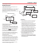
Installation • Wiring Connecting the receiver — MV-4002 Tracking System WIRING TWO RECEIVERS Connecting one receiver 1. Mount the DC Passive D575p demultiplexer in the same cabinet as your receiver. NOT USED INPUT D575p DEMULTIPLEXER 2. Connect the coax cable from the roof to the “input” on the DC Passive D575p demultiplexer. Connect a coax cable from the “sat receiver” on the DC Passive demultiplexer. Connect other end of this cable to “satellite in” on receiver.
Troubleshooting PROBLEM The MV-4002 does not attempt to find a satellite or it never moves. SOLUTION 1. Check your Power switch to verify that it is in the ON position. 2. Make sure that the receiver is plugged in and the satellite in jack is connected to MV-4002. 3. Verify that the MV-4002 has had it’s three shipping straps removed. These straps are located inside the dome and keeps the dish from moving until it is installed.
Specifications & Warranty Features and specifications • One button operation. • 30’ power cable and 30’ coaxial cable included. • GPS satellite signal acquisition. • Dome UV protected. • Depending on receiver type, you can access satellites 119°, 110°, 101° or 92°. • Off-white color compatible with all vehicles. • Compact size — 32” diameter, 15.75” height Weight of unit - 32 lbs. Shipping weight - 44 lbs. • No user input required. • No data port required for DISH NetworkTM, DIRECTV® or ExpressVu.