Instruction Manual For Models FV-HD45/FVHD45C FreeVision® Antenna Made in U.S.A. (Designed for use with 54–698 MHz DTV frequencies.) Point Toward Stations Mast not included with antenna. WARNING Installation of this antenna near power lines is dangerous. For your safety, follow the installation instructions.
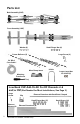
Parts List Back Assembly (VHF) Front Assembly (UHF) Washer (6) Small Flange Nut (6) Large Screw (2) Corner Reflector (2) 50’ RG-6 Coax Cable* Mast Clamp Insert Matching Transformer U-Bolt Large Flange Nut for U-Bolt (2) Low Band VHF Add-On Kit For RF Channels 2–6 and/or FM (Not Needed for Most Installations, See Page 3.) Large Screw Element Extension with Both Ends Crimped Clip Small Flange Nut (17) Element Sleeves (8) 2 Element Extensions (8) *Included in FVHD45C models only.
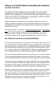
Things to Consider Before Installing the Antenna Location Selection The digital broadcast signal travels line of sight. The fewer objects between your antenna and the broadcast tower, the stronger your signal will be. Installing your antenna in the attic may reduce the signal by as much as 50% so it is always recommended to install the antenna outdoors for maximum performance.
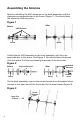
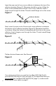
Assembling the Antenna Start by unfolding the VHF elements on the back assembly until the elements are perpendicular to the boom (Figure 1). You should hear the elements click into place. Figure 1 After Before VHF Elements Boom Boom Unfold the six UHF elements on the front assembly until they are perpendicular to the boom. See Figure 2. You should hear the pieces click into place. Pull the two phasing lines away from the boom.
Slide the crimped end of the front assembly boom into the open end of the back assembly boom (Figure 4). Re-insert the screw into the plastic block closest to the mast clamp, and secure with the flange nut. Figure 4 Front Assembly Back Assembly Crimped End Screw Insertion Mast Clamp Site Then, slip the phasing lines onto the threaded rivets near the reflector brackets. Add a washer onto each rivet. Thread a small nut onto each rivet. See Figure 5.
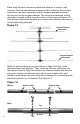
Insert the open end of one corner reflector in-between the top of the reflector brackets (Figure 7). (Elements should be on top.) Align the holes in the brackets with the hole in the corner reflector. Insert a large screw through the holes. Thread a small flange nut on the screw. Figure 7 Reflector Brackets Next, insert the open end of the second corner reflector in-between the bottom of the reflector brackets (Figure 8). (Elements should be on bottom.
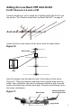
Adding the Low Band VHF Add-On Kit For RF Channels 2–6 and/or FM If unsure whether or not to install the Low Band VHF Add-On Kit, see the section “Do I Need to Install the Low Band VHF Kit?” on page 3. Locate the hole in the bottom of the boom near the mast clamp. Figure 10 Mast Clamp Hole Insert the large screw through the hole in the bottom of the boom (Figure 11). Place the element extension with crimped ends onto the screw.
Place each element extension beside the element to which it will connect. The shortest element extension will connect to the shortest element on the back assembly, and the longest element extension will connect to the longest element. The element extensions should decrease in length as they near the center of the antenna (Figure 12). One element sleeve will be used to connect each element extension to its corresponding element.
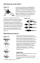
Attaching the Coax Cable* Figure 14 Posts Locate the two posts on the underside of the front assembly (Figure 14). Place two washers on each post. Loosely thread a small nut onto each post. Slide one fork of the matching transformer between a set of washers. Repeat for the other fork on the other post. Tighten the nuts, making sure that the forks are still connected. Remove the rubber boot from the matching transformer. Slide the rubber boot over the coax cable and install the connector.
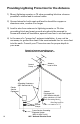
Providing Lightning Protection for the Antenna 1) Mount lightning arrestor or 75 ohm grounding block as close as possible to where lead-in enters house. 2) Ground wires for both mast and lead-in should be copper or aluminum wire, number 8 or larger. 3) Lead-in wire from antenna to lightning arrestor or 75 ohm grounding block and mast ground wire should be secured to house with stand-off insulators, spaced from four to six feet apart.
Amplifying the Signal The signal received at the antenna is all the signal the system will ever have; amplifiers can only prevent losing this signal as it runs to one or more televisions. Therefore, mounting location and direction are very important. An amplifier or proamplifier may be required if either of the following applies: • The cable between the antenna and the television is longer than 50 feet. • More than one television is connected to the antenna.
90 DAY LIMITED WARRANTY Winegard Company warrants this Winegard product against any defects in materials or workmanship within 90 (ninety) days from date of purchase. No warranty claim will be honored unless at the time the claim is made, you present proof of purchase to an authorized Winegard dealer (if unknown, please contact Winegard Company, 3000 Kirkwood Street, Burlington, IA 52601-2000, Telephone 800-288-8094).
Manual de Instrucciones Para los Modelos FV-HD45/FVHD45C Antena FreeVision® Fabricada en Estados Unidos (Diseñada para usarse con frecuencias DTV de 54–698 MHz.) Apunte Hacia las Estaciones El mástil no se incluye con la antena. ADVERTENCIA La instalación de esta antena cerca de líneas eléctricas es peligrosa. Por su seguridad, siga las instrucciones de instalación.
Lista de Partes Conjunto Trasero (VHF) Conjunto Delantero (UHF) Arandela (6) Tuerca de Brida Pequeña (6) Reflector de Esquina (2) Tornillo Grande (2) Cable Coaxial RG-6 de 50’ Inserto de la Abrazadera del Mástil Transformador de Acoplamiento Perno U Tuerca de Brida Grande para Perno U (2) Kit Adicional de VHF de Banda Baja para los Canales 2–6 de RF y FM (No se Necesita para la Mayoría de las Instalaciones, Consulte la Página 3.
Lo que se Debe Considerar Antes de Instalar la Antena Selección de la Ubicación La señal de transmisión digital viaja en la línea de la visión. Entre menos objetos haya entre su antena y la torre de transmisión, más fuerte será su señal. Instalar su antena en el ático puede reducir la señal hasta en un 50%, de manera que siempre se recomienda instalar la antena al aire libre para obtener el máximo rendimiento.
Ensamble de la Antena Inicie desplegando los elementos VHF en el conjunto trasero hasta que los elementos estén perpendiculares a la pluma (Figura 1). Debe escuchar que los elementos hacen clic en su lugar. Figura 1 Después Antes Elementos VHF Pluma Pluma Despliegue los seis elementos UHF en el conjunto delantero hasta que estén perpendiculares a la pluma. Vea la Figura 2. Debe escuchar que las piezas hacen clic en su lugar. Separe las dos líneas de ajuste de fase de la pluma.
Deslice el extremo encapsulado de la pluma del conjunto delantero en el extremo abierto de la pluma del conjunto trasero (Figura 4). Vuelva a insertar el tornillo en el bloque de plástico más cercano a la abrazadera del mástil, y asegure con la tuerca de brida. Figura 4 Conjunto Delantero Extremo Encapsulado Conjunto Trasero Sitio de Inserción Abrazadera del Tornillo del Mástil A continuación, deslice las líneas de ajuste de fase sobre los remaches roscados cerca de los soportes del reflector.
Inserte el extremo abierto de un reflector de esquina en medio de la parte superior de los soportes del reflector (Figure 7). (Los elementos deben estar en la parte superior.) Alinee los orificios en los soportes con el orificio en el reflector de esquina. Inserte un tornillo grande a través de los orificios. Enrosque una tuerca de brida pequeña sobre el tornillo.
Agregando el Kit Adicional VHF de Banda Baja Para Canales 2–6 de RF y FM Si no está seguro si debe instalar o no el Kit Adicional VHF de Banda Baja, consulte la sección “¿Necesito Instalar el Kit VHF de Banda Baja?” en la página 3. Localice el orificio en la parte inferior de la pluma cerca de la abrazadera del mástil. Figura 10 Abrazadera del Mástil Orificio Inserte el tornillo grande a través del orificio en la parte inferior de la pluma (Figura 11).
Coloque cada extensión de elemento al lado del elemento al que se conectará. La extensión de elemento más corta se conectará al elemento más corto en el conjunto trasero, y la extensión de elemento más larga se conectará al elemento más largo. Las extensiones de elemento disminuirán en longitud a medida que se acercan al centro de la antena (Figura 12). Se utilizará una camisa de elemento para conectar cada extensión a su elemento correspondiente.
Sujeción del Cable Coaxial* Figura 14 Postes Localice los dos postes en la parte inferior del conjunto delantero (Figura 14). Coloque dos arandelas en cada poste. Enrosque sin apretar una tuerca pequeña sobre cada poste. Deslice una horquilla del transformador de acoplamiento entre un juego de arandelas. Repita el proceso para la otra horquilla en el otro poste. Apriete las tuercas, asegurándose de que las horquillas aún se encuentran conectadas. Quite la bota de hule del transformador de acoplamiento.
Proporcionando Protección Contra Relámpagos para la Antena 1) Monte el pararrayos o el bloque de conexión a tierra de 75 ohmios tan cerca como sea posible a donde la introducción entra a la casa. 2) Los cables de conexión a tierra para el mástil y la introducción deben ser de cobre o de aluminio, número 8 ó mayor.
Amplificando la Señal La señal recibida en la antena es toda la señal que el sistema siempre tendrá; los amplificadores sólo pueden evitar la pérdida de esta señal cuando pasa a una o más televisiones. Por lo tanto, la ubicación y la dirección del montaje son muy importantes. Para cualquiera de las siguientes aplicaciones se puede requerir un amplificador o un amplificador profesional: • El cable entre la antena y la televisión es más largo que 50 pies.
GARANTÍA LIMITADA DE 90 DÍAS Winegard Company garantiza que este producto Winegard está libre de cualquier defecto en los materiales o fabricación del mismo durante 90 (noventa) días a partir de la fecha de compra. No se aceptarán reclamos salvo que al momento del mismo, presente prueba de compra a un distribuidor autorizado de Winegard (si lo desconoce, por favor contacte a Winegard Company, 3000 Kirkwood Street, Burlington, IA 52601-2000, Teléfono 800-288-8094).