WINEGARD® TRAV’LER ® Automatic Multi-Satellite TV Antenna Model SK-7002 INSTALLATION MANUAL ICpaE ny HO Com C W HA R AS A AR ST 4-ST 8 55 1 88 SK-7002 Winegard Company • 3000 Kirkwood St. • Burlington, IA 52601-2000 319/754-0600 • FAX 319/754-0787 • www.winegard.com Printed in U.S.A. © Winegard Company 2008 2452159 Rev.
Congratulations! You have selected the Winegard® TRAV’LER Automatic Multi-Satellite TV Antenna. The TRAV’LER antenna will deliver the ability to view both SHAW DIRECT satellites at the same time with unmatched signal strength, the lowest travel height on the market, maximum HD capabilities and easy to use functionality – just like you get at home. This manual provides important information on the installation and operation of your TRAV’LER Interface Box.
Plan your entire installation before you start. Determine the location of all of your equipment and make sure cable and wires are long enough to reach their destination points. 3/16” You must find a location on the roof that provides adequate space to allow the TRAV’LER antenna to operate. The TRAV’LER antenna has a Front and Back and must be mounted correctly to avoid damage to the TRAV’LER antenna or the coach.
3. The unit must be within 5° of level for best operation. 4. Make sure that the location offers enough support to attach the TRAV’LER antenna securely. 5. Find a well ventilated location with a 110 V outlet for the TRAV’LER Interface inside the vehicle. Make sure to clean the installation area before you begin. You will want to decide where the wires will enter the vehicle. One coax cable per receiver and a control cable will need to be run into the vehicle.
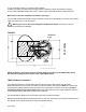
DO NOT SEAL FIGURE 4 LIP OF TRANSITION PLATE ! WARNING: DO NOT cut any wires when you drill the hole for your cables. SEAL Run a solid bead of sealant around the transition plate, making sure to cover each screw head. Be careful not to get any sealant above the lip of the transition plate. See diagram of transition plate. GPS Installation: The GPS antenna is connected to the TRAV’LER by a 6’ cable running to Port E on the TRAV’LER Mount.
Cable installation: Connect the control cable and power cable to the back of the TRAV’LER Interface box as shown below. Note: For cable runs longer than 25’ an extension may be purchased. Do not exceed 50’ of cable. Power ` Control Cable ` FIGURE 5A Attach the TRAV’LER control cable to the TRAV’LER Interface Box, as shown in Figure 5A. Attach the output cable from the Power supply to the TRAV’LER Interface Box. See above.
A. Press [ENTER] the TRAV’LER will return to the “Installation Menu” OR B. Press [POWER] the TRAV’LER will stow and turn “OFF” (Restart at Step 1). Refer to the SKA-722 Manual for instructions on how to install the Reflector and Bracket. Manual: 1. Press [POWER] and hold for 2 seconds to turn “ON” the TRAV’LER Interface Box. Wait until the Interface Box finishes “connecting to antenna”. * The TRAV’LER may enter the “Search Routine” after 10 seconds this is normal (See NOTE Below). 2.
WARNING: Pay attention to these Pinch Points as the antenna raises! NOTE: Pinch Points are called out both for your safety and to protect the cables. Cables will be damaged if installed incorrectly. Refer to the SKA-722 installation manual Pages 3-4 for proper cable attachment. FIGURE 6 FIGURE 7 Pinch Points Pinch Point Pinch Point Using the (4) bolts and nuts provided, attach the reflector to the mounting bracket. Press [POWER] to lower the antenna to the travel position.
Appendix: Making the Right Connection with Hex Connectors Making a coaxial cable connection is critical. If you have the basic technique right you can modify it to your own personal taste. Whether you use a knife, stripping tool or diagonal cutter, the important thing is to make a good clean cut. A hex crimping tool is required for hex connectors, for maximum RF transmission. As mentioned before, the choice of tools is yours. Be sure you do a precise job.
WINEGARD MOBILE PRODUCTS LIMITED WARRANTY (2 YEARS PARTS; 1 YEAR LABOR) Winegard Company warrants this product against defects in materials or workmanship for a period of two (2) years from the date of original purchase. During year one (1) of such warranty, Winegard Company will also pay authorized labor costs to an authorized Winegard dealer to repair or replace defective products.
INSTALLATION 11
Winegard Company • 3000 Kirkwood St. • Burlington, IA 52601-2000 319/754-0600 • FAX 319/754-0787 • www.winegard.com Printed in U.S.A. © Winegard Company 2008 2452159 Rev.