OWNER’S MANUAL - OPERATION/INSTALLATION INSTRUCTIONS ® WINEGARD RV Digital Satellite System with RS-1000 Antenna Model RM-4610, no Digital Magic Elevation Sensor Model RM-DM61 with “Digital Magic” Elevation Sensor Model RM-DM55 with “Digital Magic” (No Power Supply) TM TM TM U.S. PATENT NO. 5,532,710 AND 5,554,998 Made in U.S.A.
OPERATION FINDING THE SATELLITE TUNING ANTENNA FOR THE BEST PICTURE STEP 1. Your receiver should indicate it is receiving a signal. To tune your antenna, slowly move the antenna left, then right, until you find the position with the highest signal strength. It is important to turn the antenna slowly. Because the signal is digital, it takes a few seconds for the receiver to lock on. STEP 2. Place rotation clamp in the LOCK position. This prevents the antenna from moving and losing signal. STEP 3.
OPERATIONS DO’S AND DON’T’S DO’S 1. Do check parking location for obstructions before raising antenna. DON’T’S 1. Don’t move RV/Coach with the antenna in the UP position. This will VOID your warranty. This may also cause damage to your roof. 2. Do carefully raise, lower and rotate the antenna — if difficult, check for cause. 2. Don’t force the elevating crank up or down. Check for the cause. 3. Do rotate slowly when searching for the satellite(s) and check fine tuning on TV set for proper adjustment.
TROUBLE SHOOTING NO PICTURE ON TV 1. Do you have a clear line of sight to the satellite? Are there trees, buildings, etc. in the way? Figure 3 illustrates the look angle of your reflector. FIGURE 3 2. Do you have the menu from the receiver? If not, check the channel the TV set is tuned for — it should be 3 or 4. Reflector at 90° 3. Check connections at the receiver, TV and antenna. Sig NO SIGNAL FOUND 1.
INSTALLATION AND ASSEMBLY THINGS YOU NEED Screwdrivers (Phillips and slot) 1-3/4” hole saw 7/16” wrench Drill with 1/8” bit Tape measure Sealant (Must be approved for compatibility w/roof) STEP 1. Choose a location on the roof for the unit. The dish must be able to rotate without interfering with other roofmounted equipment (air conditioners, etc.), Figure 4. Be sure the interior ceiling plate is easily accessible with no obstructions that may interfere with operation.
STEP 3. Remove backing from gasket. Attach adhesive side to base plate. IF YOU ARE USING THE ROOF WEDGE (RW-5000), use 3/16” gasket included with the mount UNDER the roof wedge. Install the 1/16” gasket included with RW-5000 BETWEEN the mount and roof wedge.See Figure 7. The word FRONT is embossed on the base. This MUST FACE the front of the vehicle. Secure to roof using two mounting PINS screws provided. Check inside the vehicle. Be sure the shaft is centered in the hole. Attach crank handle to shaft.
STEP 7. Facing the front of the dish, find coax cables attached to side of the feed arm, Figure 9. Measure 24” of coax from this point and mark. DO NOT CUT. Rotate mount on base clockwise, fully, until it stops. Route coax around mount base, Figure 10. FIGURE 9 Measure coax 24” from plastic tie wrap on left side of feed arm. (STEP 7) Fasten cable clamp in hole in mount base (check roof template inserted in this manual for correct location) at end of the coax cable measurement. FIGURE 10 STEP 8.
FOR RM-DM61/RM-DM55 ONLY DIGITAL ELEVATION SENSOR ROOF CONNECTIONS The illustrations below show the different methods of connecting wires at roof level. Method will depend on model. Wire colors MUST MATCH (i.e. red to red, green to green, black to black, white to white). This wire harness connects to the digital elevation sensor on the antenna. Snap connectors together NOTE: This terminal is NOT weatherproof and CANNOT be left outside on the roof. Supplied with the DM-2000 only.
WITH ROOF WEDGE WITHOUT ROOF WEDGE Measure from top of roof wedge to ceiling. TOP OF ROOF WEDGE Measure from top of roof to ceiling. ³ TOP OF ROOF ³ STEP 19. The directional handle and threaded rod will fit roofs up to 5-1/4" thick. If you are using wedges to compensate for roof/ ceiling slope, be sure to allow for this extra thickness. You may add an extension to the directional handle for thicker roofs. Each extension will increase the length of the directional handle by 2-1/4".
CAUTION: After INITIAL INSTALLATION, the antenna should ROTATE APPROXIMATELY 360° FROM TRAVEL POSITION. FIGURE 15 The pointer on the DIRECTIONAL HANDLE should point towards the RED SCREW on the ROTATION CLAMP when in TRAVEL POSITION.
4/22/02 Feed Arm Interior Wall Plate Display Unit Roller Hex Head Bolt 1/4-20 x 2.
PARTS LIST INTERIOR HARDWARE KIT RK-CEIL Ceiling Base Directional Dial (4) #10 Phillips Flat Head Screws Azimuth Lock Azimuth Lock Knob Directional Handle Extension Washer #10 x 3/8" Red Phillips Screw Directional Handle CRANK HANDLE KIT RK-HAND #8-32 x 3/8" Phillips Screw Crank Handle Base #8-32 Square Nut Crank Handle Knob #10 x 3/8" Phillips Screw Washer NOT TO SCALE Rev 6/11/01 12
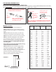
SPECIFICATIONS Height when raised ........ 30” with satellite antenna in vertical position Height in travel position ........ 8” Operating radius ........ 35” (70” diameter circle) Roof space required ........ 19.5” x 46.75” LNBF ........ Compatible with DISH Network®, DirecTV® and ExpressVu Color ........ White Satellite antenna height ........ 20.9” Satellite antenna width ........ 19.5” F/D ........ 0.59 Offset angle ........ 24° Satellite antenna gain— 11.2 GHz ........ 33.22 dBi 12.1 GHz ........ 33.
REPLACEMENT PARTS KITS HEAD ASSEMBLY RP-RS00 Head w/bracket and nut ................ 1 Pins .............................................. 2 E-Clip ............................................ 2 TURRET ASSEMBLY RP-9500 Spring ............................................ 1 Roll Pin ......................................... 1 Gear for worm shaft ...................... 1 Elevation gear ............................... 1 Bushing ......................................... 2 Seal ..................................
WINEGARD MOBILE PRODUCTS LIMITED WARRANTY (2 YEARS PARTS; 1 YEAR LABOR) Winegard Company warrants this product against defects in materials or workmanship for a period of two (2) years from the date of original purchase. During year one (1) of such warranty, Winegard Company will also pay authorized labor costs to an authorized Winegard dealer to repair or replace defective products.