
Information Sheet

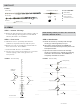


WARNING: Be sure the phasing lines DO NOT touch the
metal bracket or the antenna boom. See FIGURE 4.
NOTE: The HD8200U antenna tuning stubs do not need
to touch the boom.
STEP 4 - Attaching Front Section to Rear Section
A. Slide the front boom into the rear boom making sure
to feed the UHF phasing lines into the holes near the
top of the cartridge housing, and into the slotted pegs
inside the housing. See FIGURE 4. When finished, the
phasing lines will be resting in the slots of the pegs,
but will not extend out the back side of the cartridge
housing.
B. Reinstall the director element, bolt and nut. See
FIGURE 2.
STEP 5 - Cartridge Housing
A. Attach the cartridge housing cover so all 4 snaps are
locked in place. Direction of the housing does not
matter. See FIGURE 5.
STEP 6 - Corner Reflector Assemblies
A. Unfold the elements on the corner reflector booms.
Element clip tips should point away from the open end
of each boom. See FIGURE 6.
B. Attach the corner reflector booms using the supplied
nuts and bolts. See FIGURE 6
STEP 7 - Boom Brace
A. Install the boom brace by first removing the bolts and
hex nuts.
B. With the cartridge housing facing down, install the
boom brace to the top corner reflector boom first,
making sure the mast clamps are on the same side. See
FIGURE 7. Only finger tighten the bolt and
hex nut.
C. Swing the other end of the boom brace down onto the
rear section and insert the bolt and hex nut.
D. Tighten both bolts and nuts (on each end of the boom
brace) securely.
FIGURE 4 - Front Section to Rear Section
FIGURE 5 - Attach Cartridge Housing
FIGURE 6 - Corner Reflector Assemblies
FIGURE 7 - Boom Brace Installed
Cartridge Housing
UHF Phasing Lines
Cartridge Housing
V-shaped
tuning stub
Element Clip Tips
Pointing away from
open end of boom
Attach the corner
reflector booms
Install this
end first
Install this
end last
Mast
Clamps
Cartridge Housing,
(Facing Down)
Be sure the phasing
lines DO NOT touch
the metal bracket or
the antenna boom.