www.winemate.com Wine Cooling System WM-1500HTD WM-1500HTD-TE WM-2500HTD WM-2500HTD-TE Installation, Use & Care Manual www.vinotemp.
Important Safety Information • • • DO NOT PLUG IN UNTIL 24 HOURS AFTER DELIVERY. DO NOT USE A GROUND FAULT INTERRUPTER (GFI). A DEDICATED 20 AMP CIRCUIT IS REQUIRED.
Table of Contents Features & Specifications.…………………….……………..3 Installation Instructions..……………………………………..5 Temperature and Humidity……………..…………………..12 Care Guide…………………………………………..………16 Troubleshooting……………………………………………..17 Wiring Diagram……………………………………….………20 Customer Support……………………………………………22 Warranty……………………………………………………….
Features and Specifications • • • • • • • • • • WM-1500HTD, HTD-TE and WM-2500HTD, HTD-TE cooling units are designed and used to provide a subtle temperature between 50~65 °F for a properly insulated wine cabinet. The refrigerated space will maintain humidity range within 50~70% RH. These temperature and humidity ranges are optimized for long term storage of wine. Temperature is controlled and humidity is adjusted using patented technology.
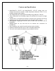
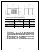
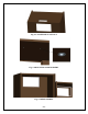
Fig. 1.2 DIMENSIONS (in) The specifications and dimensions are listed as follows: Model Exhaust WMRear Exhaust 1500htd WMTop Exhaust 1500htd-te WMRear Exhaust 2500htd WMTop Exhaust 2500htd-te CFM Cabinet Size (cu ft) Electrical Weight (lb) 120 90 115V/60Hz/4A 55 120 90 115V/60Hz/4A 55 180 200 115V/60Hz/5A 60 180 200 115V/60Hz/5A 60 NOTES: • Also see the voltage, frequency and current specified on the label at the cooling unit.
Installation Instructions NOTES: • Mounting brackets, screws, gaskets and other seal materials are not included. • Do not install any ducts onto the supply, return, intake and exhaust. • Because of potential safety hazards under a certain condition, we strongly recommend against the use of an extension cord.
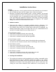
• • • • • • • • • • ambient-air intake and hot-air exhaust must not be short-circulated. A piece of wood may be used to separate them. Cut a rectangular inside opening at the rear of the cabinet with the 1/4” clearance inwards to the width and height of the cooling unit. By not going through, leave 1/2” lip inside at the wall to place the gaskets (see Fig. 2.1 & 2.2). If top exhaust installation, cut another rectangular opening at the top of the cabinet to the length and width of the top exhaust (see Fig.
Fig. 2.1 CUTOUT AND HOLE DIMENSIONS Fig. 2.
Fig. 2.3 TOP EXHAUST CUTOUT Fig. 2.4 MOUNTING SCREW INSERT Fig. 2.
Fig. 2.
Fig. 2.
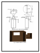
Fig. 2.8 COOLING UNIT MOUNTED (REAR EXHAUST) Fig. 2.
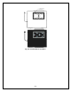
Temperature and Humidity 1. Use of the controller Fig. 3.1 TEMPERATURE CONTROLLER 1) Keys SET: To display target set point; in programming mode it selects a parameter or confirm an operation. (DEF): To start a manual defrost. (UP): To see the maximum stored temperature; in programming mode it browses the parameter codes or increases the displayed value. (DOWN): To see the minimum stored temperature; in programming mode it browses the parameter codes or decreases the displayed value.
4) Alarm Signals The alarm codes are described as follows.
5. How to calibrate the air probe If the actual cellar temperature differs from the displayed temperature, set ot = actual cellar temperature minus displayed temperature. 6. How to adjust defrost cycle 1) In case the cooling unit does not stop, the parameters FnC = C-n, idF =4 and MdF = 30 can be used to cycle off. 2) In case there is excessive frost, the parameters FnC = C-y, idF = 6 and MdF = 20 can be used to avoid defrost. 7.
3) Press up/down keys / to scroll to the required parameter within 10 sec. 4) Press the “SET” key to display its value. to change its value within 10 sec. 5) Use up/down keys 6) Press “SET” to store the new value. 7) To exit: Press SET + or wait 15sec without pressing a key.
Care Guide 1. Cleaning Condenser • • • Clean the condenser regularly at least every 6 months. Condenser is located on the ambient air intake side of the cooling unit. Use a condenser brush or a vacuum cleaner with an extended attachment to clean the condenser. 2. Removing Condensate Remove the excessive condensate if it is accumulated on the cooling unit in high humidity conditions. 3. Removing Unit When you remove the cooling unit, beware water may come out of the unit.
Troubleshooting This Troubleshooting Chart is not prepared to replace the training required for a professional refrigeration service person, not is it comprehensive Complaint 1. Unit not running 2. Unit not starting , but temperature rising high 3. Temperature fluctuating 4. Temperature high, unit stopping and starting normally 5. Temperature high, unit stopping and starting with short running time 6. Temperature Possible Causes a. b. c. d. e. f. g. h. i. a.
high or not cooling and running continually seal b. Cabinet too large c. Ambient temperature too high d. Exhaust restricted e. Malfunctioning fans 7. Unit running too long f. Evaporator or condenser airflow g. h. i. j. k. l. Dirty Condenser Iced evaporator Refrigeration system restriction Refrigerant leak Undercharge or overcharge Failed components a. Improper cabinet insulation & seal b. Exhaust restricted c. Cabinet too large d. Ambient temperature higher > 90°F e. Dirty Condenser f.
13.Evaporator freezing up 14.Water leak 15.Circuit tripping 16.Noisy operation d. Temperature controller fault d. Change a new one a. Evaporator air flow restriction b. Condenser air flow restriction c. Not stopping due to air leak, high ambient temperature, low temperature setting or pull-down cooling d. Defective controller or probe e. Low ambient temperature f. Initially working then stopping, moisture in the system g. Refrigerant low or leaking h. Capillary tube blockage a.
Wiring Diagram Fig. 6.
Fig. 6.
Customer Support If you need further assistance, please contact us at: Vinotemp International 17631 South Susana Road Rancho Dominguez, CA 90221 Tel: (310) 886-3332 Fax: (310) 886-3310 Email: info@vinotemp.
Warranty Thank you for choosing a Vinotemp cooling unit. Please enter the complete model and serial numbers in the space provided: Model_________________________________________________________ Serial No.______________________________________________________ Attach your purchase receipt to this owner’s manual. 1. Limited Warranty VINOTEMP warrants its products to be free from defects due to workmanship or materials under normal use and service, for twelve months after the initial sale.
is determined to be faulty and is within the twelve month warranty period VINOTEMP will, at its discretion, repair or replace the unit and return it free of charge to the original retail customer. If the unit is found to be in good working order, or beyond the initial twelve month period, it will be returned freight collect. 2. Limitation of Implied Warranty VINOTEMP’S SOLE LIABILITY FOR ANY DEFECTIVE PRODUCT IS LIMITED TO, AT OUR OPTION, REPAIRING OR REPLACING OF UNIT.