www.winemate.com Rack Split Cooling System Installation, Operation & Care Manual WM-2500SSRWC WM-4500SSRWC WM-6500SSRWC www.vinotemp.
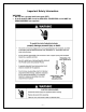
Important Safety Information WARNING: • Do not use a ground fault interrupter (GFI). • A dedicated 20 AMP circuit for WM-2500~4500SSRWC and 30 AMP for WM-6500SSRWC are required.
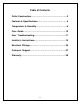
Table of Contents Cellar Construction.…………………………….……………..3 Features & Specifications…………………….….…………..4 Temperature & Humidity……….…………..………..……….6 Care Guide……………………………………………………10 User’ Troubleshooting…….………………………………...11 Installer’s Instructions………….…..….……..…………….15 Electrical Wirings..…………….…..….……..………………25 Customer Support……………………………………………27 Warranty……………………………………………………….
Cellar Construction This is only a guide and shall be considered as minimum requirements. All interior walls and floors shall have a vapor barrier and a minimum of R13 insulation. All exterior walls and ceiling shall have a vapor barrier and a minimum of R19 insulation. The vapor barrier shall be installed on the warm side of the insulation.
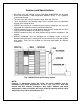
Features and Specifications • • • • • • • Wine-Mate rack split cooling systems WM-2500~6500SSRWC are designed and used to provide a cold temperature between 50~65 °F for a properly insulated wine cellar. The wine cellar will maintain humidity range within 50~70% RH. These temperature and humidity ranges like in natural caves are optimized for long term storage of wine. SSRWC units consist of a condensing unit and an evaporator unit; they are connected by a liquid line and an insulated suction line.
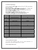
NOTE: To prepare rough-in, leave minimum 4” clearances for electrical wiring and refrigeration piping. The specifications and dimensions are listed as follows: Model No WM-2500SSRWC WM-4500SSRWC WM-6500SSRWC Evap Unit L”xD”xH” Cond Unit L”xD”xH” WM-25SFCR 32x11.125 x11.375 WM-45SFCR 38x11.125 x14.375 WM-65SFCR 38x11.125 x14.
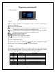
Temperature and Humidity 1. The controller Fig. 2 TEMPERATURE CONTROLLER 1) Keys SET: To display set-point; in programming mode it selects a parameter or confirms an operation. : To start a manual defrost. : To see the maximum stored temperature; in programming mode it browses the parameter codes or increases the displayed value. : To see the minimum stored temperature; in programming mode it browses the parameter codes or decreases the displayed value. : To turn on/off the power to the unit.
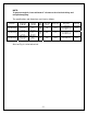
4) Alarm Signals The alarm codes are described as follows.
6. Parameter Programming 1) Press and hold the SET + keys until the “°C” or “°F” LED starts flashing, then release the keys. 2) Press and hold again the SET + keys until the Pr2 label is displayed, then release the keys. The first parameter Hy will be displayed. 3) Press up/down keys / to scroll to the required parameter within 10 sec. 4) Press the “SET” key to display its value. 5) Use up/down keys to change its value within 10 sec. 6) Press “SET” to store the new value and the display will flash 3 times.
In case there is excessive frost, the parameters FnC = C-y, idF = 4 and MdF = 20 can be used to avoid frost. 9. How to adjust the humidity The parameter Fon is used to adjust the humidity in the wine cellar. Higher Fon results in higher relative humidity. Use a separate hygrometer to monitor the humidity. 10. How to set alarm call 1) Speech notice will be sent to your phones when the cellar temperature is ALU higher or ALL lower than the set-point Set.
Care Guide In general, always unplug system or disconnect power while doing care. 1. Condenser Water Line Cleaning • • To clear any sediment that may accumulate, the water regulating valve may be manually flushed. Insert screwdrivers under both sides of the valve spring guide and lift upwards to flush. 2. Condensate Removing • Remove the excessive condensate if it is accumulated in the wine cellar at high humidity conditions.
User’s Troubleshooting This Troubleshooting Chart is not prepared to replace the training required for a professional refrigeration service person, not is it comprehensive. Complaint 1. Unit not running 2. Unit not starting , but temperature rising high 3. Temperature fluctuating 4. Temperature high, unit stopping and starting normally 5. Temperature high, unit stopping and starting with short running time 6. Temperature Possible Causes a. b. c. d. e. f. g. h. i. a.
high or not cooling and running continually b. Cellar too large c. Ambient temperature too high d. Exhaust restricted e. Malfunctioning fans 7. Unit running too long f. Evaporator or condenser airflow g. h. i. j. k. l. Dirty Condenser Iced evaporator Refrigeration system restriction Refrigerant leak Undercharge or overcharge Failed components a. Improper cellar insulation & seal b. Exhaust restricted c. d. e. f. 8. Condenser fan running but compressor not running 9.
fan running but condensing unit not running 13.Temperature low b. Failed components c. b. Check start relay, start capacitor, overload protector, compressor. c. Call service Low refrigerant a. Low temperature setting b. Low ambient temperature c. Air probe fault d. Temperature controller fault a. Raise the setting b. Move to another location c. Check probe connections or change a new one d. Change a new one a. Check for fans and CFM b. Check for fans and CFM c.
high ambient temperatures or airflow restriction d. Defective components - 14 - d.
Installer’s Instructions Federal law requires that WINE-MATE split cooling systems be installed by an EPA certified refrigeration technician. 1. General Instructions WINE-MATE split system is shipped as components and is ready for use only after a certified refrigeration technician has properly installed the system. Proper installation is critical. Vinotemp can only warrant the quality of the components. The installation and proper operation of the system must be warranted by the installer.
CAUTION: Liquid and suction line locations may differ from what are shown here, please check on the units for proper installation. Fig.
Fig. 4 WM-250~850SCU-WC Condensing Unit Fig. 5 Liquid Filter Fig.
Fig. 7 Temperature Controller (4.25”L X 3.75D X 4.25”H) 2. Temperature Controller and Air Probe 1) The temperature controller can be mounted either inside or outside the wine cellar, but the air probe must be located inside the wine cellar. 2) The air probe shall be located in the wine cellar 5 ft above the floor or the air return area, but it shall not be located in the air supply area or other areas where air is not circulated.
amount of water must be provided for constant head pressure and proper cooling, but excessive water flow will cause the unit working inefficiently. 3) The maximum permissible water pressure is 150 PSIG. If water pressure is excessive, a pressure reducing valve must be used to reduce the water pressure.
Head pressure setting: Cut out=230 psig; Cut in=150 psig; Differential=80 psig It may need to adjust the setting in the field to get the right cycle time. Fig. 10 Adjustable Pressure Control 6. Refrigeration Piping and Leak Testing NOTES: • The line connection sizes of liquid filter & indicator, the valve connection sizes of condensing unit and the line connection sizes of evaporator unit are not necessary the same as the listed refrigeration line sizes.
Model No WM-2500SSRWC WM-4500SSRWC WM-6500SSRWC Equivalent Line Set <= 75 FT <= 75 FT <= 75 FT Liquid Line 1/4" OD 1/4" OD 1/4" OD Suction Line 3/8” OD 1/2” OD 1/2” OD Drain Line 7/8” OD 7/8” OD 7/8” OD Recommended Charge R134a/19 OZ R134a/26 OZ R134a/32 OZ 7. Water Piping If a water pump is used, install it before the water inlet so that the condenser cooling water is fed from the discharge side of the pump.
Fig. 11 Water Regulating Valve 2) It may use a fan speed control to adjust the air flow to achieve the specified CFM. The fan will run from the minimum speed to full speed with the control knob at the lowest and highest speed position. To adjust the minimum speed, turn control knob to the lowest speed position, then rotate the setting (located on the side or front) clockwise to decrease the minimum speed or counterclockwise to increase the minimum speed.
8) If the superheat is high, check the subcooling first to know if the refrigerant charge is sufficient. If the charge is not sufficient, add more refrigerant. If the charge is good, then increase the evaporator suction pressure by turning the hex nut (5/16”) clockwise. Liquid must always be charged into the hide side when the compressor runs. 9) If the superheat is low, then decrease the evaporator suction pressure by turning the hex nut (5/16”) counter-clockwise.
Low superheat and low subcooling Low suction pressure and low to normal head pressure High superheat and normal to high subcooling u. Low suction pressure and normal head pressure High superheat and normal subcooling v. Low suction pressure and high head pressure High superheat and high subcooling t. w. Low suction pressure and high head pressure High superheat and high subcooling x. low to normal suction pressure and high head pressure Normal to high superheat and high subcooling t.
Electrical Wiring Diagrams CAUTION: • Hidden lines are the field wirings. • Use minimum 14 gauge wires for power lines. • A safety switch is always recommended for the condensing unit. Fig.
Fig.
Customer Support If you need further assistance, please contact us at: Vinotemp International 17631 South Susana Road Rancho Dominguez, CA 90221 Tel: (310) 886-3332 Fax: (310) 886-3310 Email: info@vinotemp.
Warranty Thank you for choosing a Vinotemp cooling unit. Please enter the complete model and serial numbers in the space provided: Model_________________________________________________________ Serial No.______________________________________________________ Attach your purchase receipt to this owner’s manual. 1. Limited Warranty VINOTEMP warrants its products, parts only, to be free from defects due to workmanship or materials under normal use and service for twelve months after the initial sale.
VINOTEMP will, at its discretion, repair or replace the unit and return it free of charge to the original retail customer. If the unit is found to be in good working order, or beyond the initial twelve month period, it will be returned freight collect. 2. Limitation of Implied Warranty VINOTEMP’S SOLE LIABILITY FOR ANY DEFECTIVE PRODUCT IS LIMITED TO, AT OUR OPTION, REPAIRING OR REPLACING OF UNIT.