
Manual


33
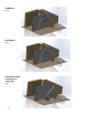
quarter inch, a vibration eliminator should be installed close to the motor compressor in a
horizontal parallel to the compressor, crankshaft or in a vertical position 90 degrees to
compressor crankshaft.
NOTE: The suction line should be clamped near the inlet end of the vibration
eliminator. The vibration eliminator is located between the clamp and the
compressor.
Split System Interconnecting Line Sizing Chart
Table 3
Model
Liquid
Line(OD)
Liquid
connection
at
evaporator
(OD)
Suction
line (OD)
Min.
Suction line
insulation
thickness
(in)
Suction
connection
at
evaporator
(OD)
Maximum
“total” line
length
Maximum
lift
(height)
SS025
1/4”
1/4”
3/8”
3/8”
3/8”
50’
15’
SS050
1/4”
1/4”
1/2”
3/8”
*3/8”
50’
15’
SS088
3/8”
*1/4”
1/2”
5/8”
1/2”
50’
15’
SS200
3/8”
3/8”
7/8”
5/8”
*1/2”
50’
15’
*Interconnecting tube must be reduced down at evaporator connection
Notes:
Line lengths are expressed in equivalent feet = actual run length + fitting allowances (i.e.
~5’ for each bend/elbow allowance).
Use only refrigeration grade dehydrated tubing.
Install refrigeration piping per local codes and ASHRAE guidelines.