
User Manual
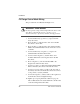
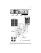
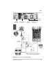
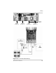
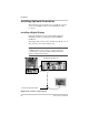
Table Of Contents
- C-Series Multifunction DC Controller
- Introduction
- Installation
- Pre-Installation
- Configuring the C-Series Controller
- Adjusting the C-Series Voltage Settings
- Equalization Charging
- Temperature Compensation
- Grounding
- Wiring
- Installing Optional Accessories
- Reinstalling the Faceplate
- Operation
- Troubleshooting
- Specifications
- Batteries
- Diversion Loads
- Diversion Load Types
- What does this warranty cover?
- What will Xantrex do?
- How do you get service?
- What proof of purchase is required?
- What does this warranty not cover?
- If you are returning a product from outside of the USA or Canada
- If you are returning a product to a Xantrex Authorized Service Center (ASC)
- A
- B
- C
- D
- E
- F
- G
- I
- J
- K
- L
- M
- N
- O
- P
- R
- S
- T
- V
- W
- X
- Diversion Load Types
Installation
50 975-0004-01-02 Rev D
Installing Optional Accessories
The following sections describe how to install the optional
accessories available for the C-Series Multifunction DC
Controller.
Installing a Digital Display
Follow the instructions in the C-Series Meter Displays
Installation Guide for preparing the CM or CM/R for
installation.
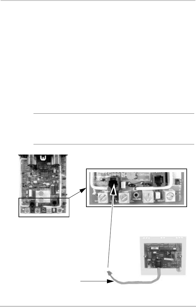
The display will connect to the controller at the RJ-15 port on
the lower left corner of the circuit board.
Important:
Ensure the voltage jumpers on the back of the CM
or CM/R match the system voltage as configured inside the
controller unit. See the C-Series Meter Displays Installation
Guide for additional information.
Figure 2-26
Installing a Digital Display
Serial Communication Cable
C-Series Circuit Board
Digital Meter Display Port
RJ-15 Port