
User Manual
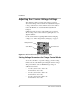
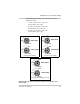
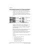
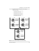
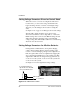
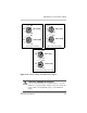
Table Of Contents
- C-Series Multifunction DC Controller
- Introduction
- Installation
- Pre-Installation
- Configuring the C-Series Controller
- Adjusting the C-Series Voltage Settings
- Equalization Charging
- Temperature Compensation
- Grounding
- Wiring
- Installing Optional Accessories
- Reinstalling the Faceplate
- Operation
- Troubleshooting
- Specifications
- Batteries
- Diversion Loads
- Diversion Load Types
- What does this warranty cover?
- What will Xantrex do?
- How do you get service?
- What proof of purchase is required?
- What does this warranty not cover?
- If you are returning a product from outside of the USA or Canada
- If you are returning a product to a Xantrex Authorized Service Center (ASC)
- A
- B
- C
- D
- E
- F
- G
- I
- J
- K
- L
- M
- N
- O
- P
- R
- S
- T
- V
- W
- X
- Diversion Load Types
Installation
22 975-0004-01-02 Rev D
Adjusting the C-Series Voltage Settings
The charging voltage setpoints and voltage reconnect/
disconnect setting of the controller are adjustable using two
rotary potentiometer controls. The knobs are removable to
reduce the likelihood of accidental mis-adjustment if
bumped.
Calibrated scales, shown as scale marks, are provided to
allow setting of the control without requiring the use of a
digital voltmeter.
For more information regarding bulk and float charging
voltages, see “Three-Stage Battery Charging” on page 4.
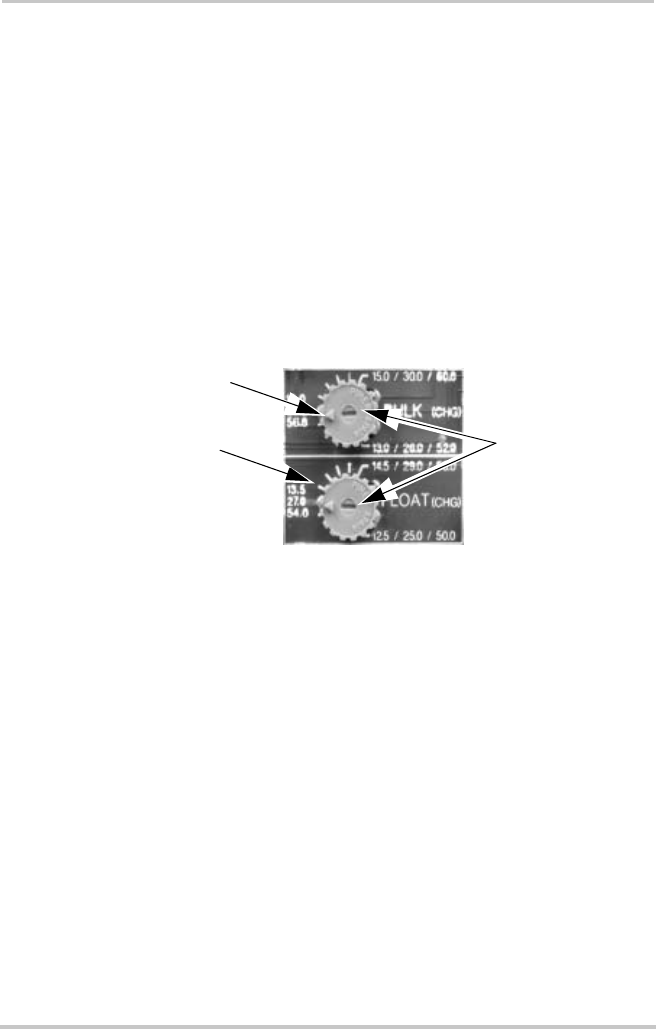
Setting Voltage Parameters for Charge Control Mode
To set the controller to a specific voltage, point the setting
indicator at the scale mark representing the desired voltage.
The potentiometer scale for BULK charge voltage is
calibrated as follows:
• 12-volt system: 13.0 to 15.0 volts
in increments of 0.2 volts,
• 24-volt system: 26.0 to 30.0 volts
in increments of 0.4 volts,
• 48-volt system: 52.0 to 60.0 volts
in increments of 0.8 volts.
Figure 2-9
Bulk and Float Charge Potentiometers (pots)
Scale Marks
Potentiometers
Setting indicator