
User Manual
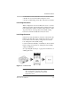
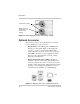
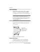
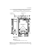
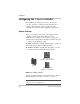
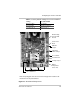
Table Of Contents
- C-Series Multifunction DC Controller
- Introduction
- Installation
- Pre-Installation
- Configuring the C-Series Controller
- Adjusting the C-Series Voltage Settings
- Equalization Charging
- Temperature Compensation
- Grounding
- Wiring
- Installing Optional Accessories
- Reinstalling the Faceplate
- Operation
- Troubleshooting
- Specifications
- Batteries
- Diversion Loads
- Diversion Load Types
- What does this warranty cover?
- What will Xantrex do?
- How do you get service?
- What proof of purchase is required?
- What does this warranty not cover?
- If you are returning a product from outside of the USA or Canada
- If you are returning a product to a Xantrex Authorized Service Center (ASC)
- A
- B
- C
- D
- E
- F
- G
- I
- J
- K
- L
- M
- N
- O
- P
- R
- S
- T
- V
- W
- X
- Diversion Load Types
Configuring the C-Series Controller
975-0004-01-02 Rev D 19
Table 2-1
Factory Default Settings for C-Series Controllers
Setting C35, C40 and C60
Battery Voltage 12 volts DC
Equalize/LVR Manual Equalization
Operating Mode Charge Control
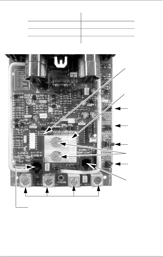
Figure 2-5
Circuit Board Components
Operating
Mode Jumper
Reset Switch
Voltage Jumpe
r
EQ/LVR
Jumper
DC Terminal Connectors
Potentiometers
Battery
Temperature
Sensor Port
NiCad Setting
Selection R46
Resistor
CM or CM/R Port
Note: This photograph shows the Load Control Voltage decal installed on the
circuit board over the potentiometers.
Load Control
Decal