
User Manual
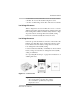
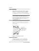
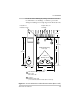
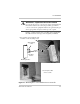
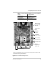
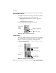
Table Of Contents
- C-Series Multifunction DC Controller
- Introduction
- Installation
- Pre-Installation
- Configuring the C-Series Controller
- Adjusting the C-Series Voltage Settings
- Equalization Charging
- Temperature Compensation
- Grounding
- Wiring
- Installing Optional Accessories
- Reinstalling the Faceplate
- Operation
- Troubleshooting
- Specifications
- Batteries
- Diversion Loads
- Diversion Load Types
- What does this warranty cover?
- What will Xantrex do?
- How do you get service?
- What proof of purchase is required?
- What does this warranty not cover?
- If you are returning a product from outside of the USA or Canada
- If you are returning a product to a Xantrex Authorized Service Center (ASC)
- A
- B
- C
- D
- E
- F
- G
- I
- J
- K
- L
- M
- N
- O
- P
- R
- S
- T
- V
- W
- X
- Diversion Load Types
Pre-Installation
975-0004-01-02 Rev D 15
knockouts before making any wiring connections. It is also
recommended to use bushings or conduits to protect the
wiring from damage from rough edges in the knockout holes.
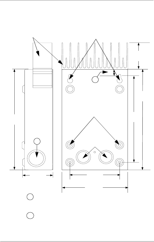
Figure 2-2
C-Series Dimensions and Knockout Locations (Not to Scale)
Side View
Rear View
8"
(203 mm)
6 7/8"
(174 mm)
8"
(203 mm
)
2"
(51 mm)
2 ¼”
(64 mm)
5”
(127 mm)
3 5/8”
(93 mm)
Heatsink not
included on C35
This distance varies per model:
C35 = 3/8"
C40, C60 = 5/8"
½ and ¾"
Dual-Knockouts
¾ and 1"
Dual-Knockouts (x4)
(1 on each side and 2 on the bottom of chassis)
Keyhole Slots for
mounting
1
2
1
2
Additional Mounting
Holes (x4)