
User Manual
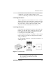
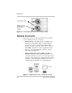
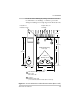
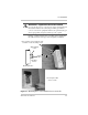
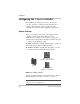
Table Of Contents
- C-Series Multifunction DC Controller
- Introduction
- Installation
- Pre-Installation
- Configuring the C-Series Controller
- Adjusting the C-Series Voltage Settings
- Equalization Charging
- Temperature Compensation
- Grounding
- Wiring
- Installing Optional Accessories
- Reinstalling the Faceplate
- Operation
- Troubleshooting
- Specifications
- Batteries
- Diversion Loads
- Diversion Load Types
- What does this warranty cover?
- What will Xantrex do?
- How do you get service?
- What proof of purchase is required?
- What does this warranty not cover?
- If you are returning a product from outside of the USA or Canada
- If you are returning a product to a Xantrex Authorized Service Center (ASC)
- A
- B
- C
- D
- E
- F
- G
- I
- J
- K
- L
- M
- N
- O
- P
- R
- S
- T
- V
- W
- X
- Diversion Load Types
Installation
14 975-0004-01-02 Rev D
Pre-Installation
The instructions that follow are applicable to the typical
installation. For special applications, consult a qualified
electrician or your Xantrex Certified Dealer. Installation
procedures will vary according to your specific application.
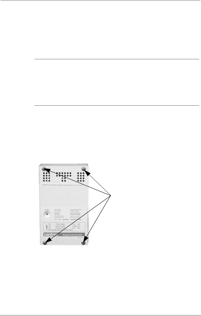
Removing the Top Cover
Access the inside of the controller by removing the four
phillips screws (#10-32 x 3/8" SMS screws) on the front
cover of the unit.
Removing Knockouts
Six dual-knockouts are provided to accommodate the
necessary wiring of the C-Series controller. Be sure to
remove any metal shavings created by removing the
Important:
Installations should meet all local codes and
standards. Installations of this equipment should only be
performed by skilled personnel such as qualified electricians and
Certified Renewable Energy (RE) System Installers. For a list of
Xantrex Certified RE dealers, please visit our website at
www.XantrexREdealers.com.
Figure 2-1
Removing the Front Cover
Remove these
phillips screws (x4)
from the front cover
to access the inside
of the controller.