SunTura Solar Tracker Kit Manual Revision 1.
SunTura Solar Tracker Kit Manual Revision 1.
SunTura Solar Tracker Kit Manual Revision 1.0 Table of Contents 1 Introduction ................................................................................................................................................. 4 1.1 Limited Warranty ................................................................................................................................ 4 1.2 Restrictions ...............................................................................................
SunTura Solar Tracker Kit Manual Revision 1.0 1 INTRODUCTION Windy Nation Inc. (“Windy Nation”) is not assembling the Solar Tracker, or any other product offered by Windy Nation. Windy Nation, and its directors, officers, and employees disclaim, and by purchasing a Windy Nation product you accept all liability and responsibility for damage to property, injury, or death arising out of or related to the use or misuse of any product offered by Windy Nation. 1.
SunTura Solar Tracker Kit Manual Revision 1.0 replaces shall become Windy Nation’s property on the date Windy Nation ships the repaired Product or part back to the Customer. Windy Nation will use all reasonable efforts within thirty (30) days of receipt of the defective Product to repair or replace such Product.
SunTura Solar Tracker Kit Manual Revision 1.0 2 PRODUCT OVERVIEW Building a complete solar tracking system has never been easier. The SunTura Solar Tracker Kit can be used directly on 12 volt or 24 volt systems. If you plan on using the SunTura Solar Tracker Kit on a grid tie system, we can supply you with a 12 volt power supply which can be plugged into the grid (110 AC or 220 AC). 2.
SunTura Solar Tracker Kit Manual Revision 1.0 geared motors that are going to be connected to the SunTura Solar Tracker Electronics and make sure each motor used does not exceed the 14 amp limit. 3.2.1 Electronics Box Installation The Electronic Box has a 20 amp fuse on the circuit board located on its inside. There is also one additional spare fuse. The fuse protects the SunTura Solar Tracker Electronics from a short circuit.
SunTura Solar Tracker Kit Manual Revision 1.0 3.2.2 North/South Linear Actuator (Motor) Installation The North/South Linear Actuator or Motor (not supplied) connects to the Green and Blue wires exiting the Electronics Box. Connect the Green wire to the DC positive port of the North/South Linear Actuator/Motor. Connect the Blue wire to the DC negative port of the North/South Linear Actuator/Motor.
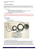
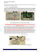
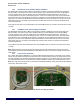
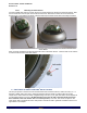
SunTura Solar Tracker Kit Manual Revision 1.0 3.2.4.1 Mounting the Photo Sensor Use the included Allen wrench to loosen the two set screws that secure the dome to the Photo Sensor. After the set screws are removed, pull off the Photo Sensor Dome. Note that it is easier to remove the Photo Sensor Dome if a flat head screw driver is used to help lift up the Photo sensor Dome. See Figure 5 below. Figure 5: Use Allen wrench to loosen set screws and remove Photo Sensor Dome with flat head screw driver.
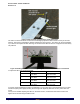
SunTura Solar Tracker Kit Manual Revision 1.0 Figure 7: Bolt mounted perpendicular to solar panel angle. The LED’s on the Photo Sensor circuit board can be slightly adjusted to fine tune the accuracy of the solar tracking. The goal is to eliminate the shadow casted by the bolt in Figure 7. The LED’s can be moved slightly up or down to accomplish this task.
SunTura Solar Tracker Kit Manual Revision 1.0 4 TROUBLESHOOTING AND SUPPORT The SunTura Solar Tracker Kit is ruggedly constructed and requires minimal care. 4.1 CARE To clean your tracker, moisten a cloth with a few drops of mild hand dishwashing detergent in a cup of lukewarm water and gently wipe clean. 4.2 TROUBLESHOOTING Problem Tracker is not accurately tracking the sun Tracker is not working Possible Remedies Follow the Fine-tuning steps included in Section 3.3 1.