P30L User Manual Revision 1.
P30L User Manual Revision 1.0 Table of Contents 1 2 3 4 5 Introduction ................................................................................................................................................... 3 1.1 Features .............................................................................................................................................. 3 1.2 Safety Information ..........................................................................................................
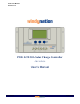
P30L User Manual Revision 1.0 1 INTRODUCTION The WindyNation P30L Solar Charge Controller provides an intelligent multifunctional charging and power management solution for the solar charging of 12 and 24 volt battery systems. Operation is conveniently presented and parameters are controlled via a customized LCD display screen interface.
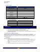
P30L User Manual Revision 1.0 1.3 SPECIFICATIONS 1.3.1 Electrical Specifications Parameter Rated Charge Current Rated Load Current Typical Idle Consumption Maximum Solar Input Voltage Rated Working Voltage Float Charging Voltage (adjustable) Low Voltage Protection (adjustable) Low Voltage Recovery (adjustable) No Load Loss Loop Voltage Drop Temperature Compensation 1.3.
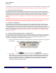
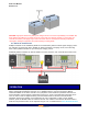
P30L User Manual Revision 1.0 IMPORTANT: For best results, mount the charge controller and batteries as close to the panels as practical. 2.3 CONNECTIONS WARNING: Loose connectors result in excessive voltage drop and may over heat wires, which can cause the wire insulation to melt. This can cause electrical fires. Verify all connections are secure and have no voltage drop.
P30L User Manual Revision 1.0 reverse polarity connections, but the charge controller will not function until the battery is connected properly. A 40 amp fuse needs to be placed in the positive wire connecting the charge controller to the battery. 2) Connect the Solar Panel (PV) Array Insert the solar panel wiring to the SOLAR terminals on the front of the charge controller and tighten the terminals from the top of the controller using a screwdriver to ensure a good connection is made.
P30L User Manual Revision 1.0 CAUTION: High power electrical systems pose dangers and it is the user's responsibility to be familiar with these dangers and take any necessary action to ensure safe use. Shorting a battery or connecting your controller to a battery can supply huge currents and have serious consequences including explosions, causing fire, damage to equipment, and personal injury including death. 2.
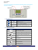
P30L User Manual Revision 1.0 is set, press the mode button for over 5 seconds to exit the setting interface, and the number will stop blinking or flickering. 3.1 BUTTON DEFINITIONS Button Name Description MODE Toggles the active LCD interface in a circular motion as defined in Sec 3.1.3 UP DOWN / LOAD Positive (+) parameter adjustments. Holding button for >5 seconds will reset parameters. Negative (-) parameter adjustments. At “MAIN” interface screen, will turn the LOAD on and off. 3.
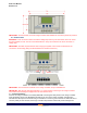
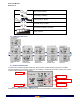
P30L User Manual Revision 1.0 Stop Charge to Battery Full Charging to Battery Float Charging to Battery Normal Working Condition Error/Abnormal Working Condition Battery Capacity 3.3 LCD INTERFACE CYCLE 3.4 INTERFACE DEFINITIONS The P30L has ten different graphical interfaces. Each interface contains different information. The Main Interface displays the current state of the Load, PV charging, Load discharging, battery capacity, and overall system working condition as shown below.
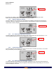
P30L User Manual Revision 1.0 LOAD ON Battery Voltage By pressing the ‘DOWN / LOAD’ button from this interface, you can turn the load ON or OFF. NOTE: The Load on/off function is not available in any other interface. 3.4.2 Battery Temperature Interface The value displayed in this interface is the temperature at the Battery Temperature Sensor (BTS) as described in Section 2.3 (displayed in degrees Celsius). The temperature is used for the temperature compensation of battery charging. BTS Temperature 3.4.
P30L User Manual Revision 1.0 Solar Generated Charge NOTE: Press the ‘MODE’ button for over 5 seconds to clear/reset the cumulative, generating charge (Ah). 3.4.6 Load Consumed Charge Interface The value displayed in this interface is the cumulative, consumed charge of the Load displayed in Amp-hours (Ah). Load Consumed Charge NOTE: Press the ‘MODE’ button for over 5 seconds to clear/reset the cumulative, consumed charge (Ah). 3.4.
P30L User Manual Revision 1.0 to adjust the parameter. After the value has been set, press the ‘MODE’ button for over 5 seconds to exit the adjustable mode and store the setting. 3.4.9 Over Voltage Disconnect Interface The value displayed in this interface is the value at which the charge controller will stop charging the battery. When the battery voltage reaches this voltage, the controller will disconnect the charging solar panel(s) to prevent the battery from overcharging.
P30L User Manual Revision 1.0 3.5 ERROR CONDITIONS 3.5.1 Low Voltage Protection If the battery voltage is lower than the protection voltage (Section 3.4.7), the controller will enter the low voltage protection state and the load will be disconnected. The use of solar panels or an alternate charger is required to charge the battery to the recovery level (Section 3.4.8).
P30L User Manual Revision 1.0 3.5.4 Solar Panel Connection If the Solar Panel Icon is blinking or flickering, it means the controller does not detect the existence of solar panels. Check that all the connections with the solar panels are making good contact and are in good condition. Check the connection terminals on the controller for any open-circuit conditions. 3.5.
P30L User Manual Revision 1.0 1. Check if the solar panel cables are connected properly. 2. Check to make sure the correct battery is being used. 3. Check all wiring connections to make sure they are in their designated The charge to battery LCD locations and make sure that there are no loose connections. indicator doesn't appear 4. Measure the PV array open-circuit voltage and confirm normal limits. when the solar panel is 5. Measure the PV voltage and the battery voltage at the controller terminals.
P30L User Manual Revision 1.0 serial number (if applicable), and the original purchase date in addition to the name, address, and telephone number of the Customer. Within five (5) business days of the date of notification, Windy Nation will provide the Customer with an RMA number and the location to which the Customer must return the defective Product. Any Product returned for warranty service shall be shipped at the expense and risk of the Customer.