Dell™ PowerApp.web 100 and PowerApp.cache 100 Appliances Rack Installation Guide This installation guide provides instructions for trained service technicians installing one or more Dell PowerApp™ 100 appliances in a rack. This guide includes procedures for the following three rack kits: • • • Two-post center-mount Two-post flush-mount Four-post rack cabinet One rack kit is required for each PowerApp 100 system to be installed in the rack.
Rack Kit Contents The rack kit includes the following items (see Figure 1): • • • Two center-mount brackets Four 10-24 x 0.375-inch pan-head Phillips (or slotted) screws Two 12-24 x 0.5-inch pan-head Phillips screws center-mount brackets (2) 12-24 x 0.5-inch pan-head Phillips screws (2) 10-24 x 0.375-inch panhead Phillips screws (4) Figure 1.
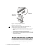
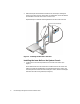
.5 inch .625 inch 1.75 inch (1 U) .625 inch .5 inch Figure 2. Two-Post Open-Frame Relay Rack 1-U Hole Spacing Attaching the Brackets 1. Locate one of the two brackets and align it over the two threaded holes on the side of the system (see Figure 3). 2. Secure the bracket to the system chassis using two 10-24 x 0.375-inch screws (see Figure 3). Repeat this step to install the remaining bracket on the other side of the system. support.dell.
10-24 x 0.375-inch pan-head Phillips screws (2 per bracket) 12-24 x 0.5-inch pan-head Phillips screws Figure 3. Securing the System in the Rack Installing the System in the Rack CAUTION: Due to the size and weight of the computer system, never attempt to install the computer system by yourself. 1. Lift the system into position between the two posts, with the hole in the mounting bracket aligned one hole above the mark you made in the two posts (see Figure 3). 2.
fasteners and bracing specified or approved by the rack manufacturer or by industry standards. Refer to the two-post open-frame relay rack manufacturer’s installation documentation for precautionary warnings and information before attempting this installation. CAUTION: Do not attempt to install the PowerApp system into a two-post open-frame relay rack that has not been securely anchored in place. Damage to the system and personal injury may result.
inner mounting rails (2) flush-mount brackets (2) 1-U template 10-24 x 0.25 inch flat12-24 x 0.5-inch panhead Phillips screws (4) head Phillips screws (4) Figure 4. Two-Post Flush-Mount Rack Kit Contents Recommended Tools and Supplies You need the following tools and supplies to install the system in a two-post openframe relay rack: • • #2 Phillips screwdriver Masking tape or a felt-tip pen, for use in marking the mounting holes to be used Marking the Rack 1.
2. Place the 1-U template over the front of the two-posts of the rack in the desired location. 3. Position the bottom of the template in line with the desired bottom position of the computer chassis. 4. Mark the upper and lower-mounting positions on the vertical rails as shown by the V-notches on the sides of the template. Each 1-U (1.75-inch) vertical space has three holes, with center-to-center spacing between holes (beginning at the center of the top hole of a 1-U space) 0.625, 0.625, and 0.
2. Slide the back part of the bracket toward the front, with the pins entering the lower screw holes in the rack, at the marks you made earlier. Secure the bracket front and back to the rack with a 12-24 x 0.5-inch screw. Repeat this step to install the remaining bracket on the other side of the rack. 12-24 x 0.5 inch screws (4) Figure 6. Installing the Bracket in the Rack Installing the Inner Rails on the System Chassis 1.
Figure 7. Securing the Inner Rails to the System Chassis 2. Secure each inner rail to the chassis using two 10-32 x 0.25-inch flat-head screws. Installing the System in the Rack CAUTION: Due to the size and weight of the computer system, never attempt to install the computer system by yourself. support.dell.com 1. Remove the optional bezel from the computer front panel. Press the tab on each end of the bezel and pull the bezel straight out from the chassis. 2.
captive fasteners Figure 8. Securing the Computer System in the Rack 5. Attach the front bezel, if one is available, to the system (see the Troubleshooting Guide for instructions). This completes the two-post flush-mount rack installation.
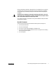
Four-Post Rack Kit Installation This procedure provides instructions for installing a Dell PowerApp 100 appliance in a four-post rack cabinet. Both 24-U and 42-U height racks are accommodated. Rack Kit Contents The rack kit includes the following items (see Figure 9): • • • • • One pair of slide assemblies One cable-management arm Four 10-32 x 0.5-inch pan-head Phillips screws Six 10-24 x 0.
cable-management arm assembly slide assemblies with mounting brackets (1 pair) 1-U template 10-32 x 0.5-inch pan-head Phillips screws (4) 10-24 x 0.375inch pan-head Phillips screws (6) Figure 9. Four-Post Rack Kit Contents Before You Begin Before you begin installing your PowerApp system in the rack, carefully read “Safety Instructions,” found earlier in this guide. NOTICE: This rack kit is intended to be installed in a Dell rack by trained service technicians.
Recommended Tools and Supplies You need the following tools and supplies to install the system in a four-post rack cabinet: • • • • A #2 Phillips screwdriver A flat-blade screwdriver An installation template, helpful in slide assembly placement and alignment Masking tape or a felt-tip pen, for use in marking the mounting holes to be used Installing the Rack Kit NOTES: If you purchased a Dell rack along with your PowerApp system, the slide assemblies may be preinstalled in the rack.
push-button cover push button handle Figure 10. Opening the 42-U Rack Door 2. 14 Remove the front door from the rack as shown in Figure 11. a. One person should grasp the top of the door to stabilize it. The other person should grasp the bottom of the door. b. The person holding the bottom of the door should press the hinge release lever on the bottom hinge and then pull the door away from the rack. c.
hinge release lever Figure 11. Removing the 42-U Rack Doors 3. Repeat steps 1 and 2 to remove the back door from the rack. Removing the Doors From the 24-U Rack CAUTION: To prevent personal injury due to the size and weight of the doors, never attempt to remove or replace the doors by yourself. support.dell.com 1. Unlock and twist the handle clockwise (see Figure 12). 2. Open the front door.
Figure 12. Unlocking the 24-U Rack Door 3. 16 Remove the front door from the rack as shown in Figure 13. a. With the door open, lift out and fully retract all hinge pins. b. Once all the hinge pins have been lifted out and retracted, lift the door out.
hinge pin hinge insert hinge Figure 13. Removing the 24-U Rack Doors CAUTION: Store the two doors where they will not injure someone if the doors accidently fall over. If you want to reverse the door so that the handle is on the other side, perform the following steps: 1. With the door open, lift out and fully retract all hinge pins. 2. Remove the hinges and door brackets from the door frame. 3. Replace the hinges and door brackets on the opposite side and switch the position of the handle. 4.
1 U (1.75 inches) Figure 14. One Rack Unit For more information about requirements for installing components in a rack, see the Dell Rack Advisor software available on the Dell World Wide Web site at: http://support.dell.com. WARNING: If you are installing more than one computer, install the slide assemblies so that the first computer is installed in the lowest available position in the rack. To install the slide assemblies in the rack, perform the following steps: 1.
1 U (1.75 inches) between slide assemblies (drawing is not to scale) 1-U template Figure 15. Using Template to Mark Vertical Rails support.dell.com 3. At the front of the rack cabinet, position one of the slide assemblies so that its mounting-bracket flange fits between the marks or tape you placed on the rack, marking the upper and lower edges of the template (see Figure 16). The hooks on the bottom of the mounting bracket should enter the holes beside the lower marks you made in the vertical rails.
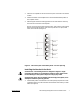
10-32 x 0.5-inch pan-head Phillips screw (2 per slide assembly) mounting-bracket flange slide assemblies (2) front of rack Figure 16. Installing the Slide Assemblies Installing the Inner Rails on the System Chassis To install the inner rails to the sides of the system, perform the following steps. CAUTION: The computer may weigh up to 15.8 kilograms (35 pounds) when fully loaded. To prevent personal injury, do not attempt to move the computer by yourself. 1.
inner rail (2) 10-24 x 0.375-inch panhead Phillips screws Figure 17. Installing the Inner Rails 2. Secure each inner rail to the side of the chassis with three 10-24 x 0.375-inch panhead Phillips screws (see Figure 17). Installing the System in the Rack WARNING: If you are installing more than one computer, install the first computer in the lowest available position in the rack. WARNING: Never pull more than one component out of the rack at a time. 1.
inner rail captive thumbscrews (2) Figure 18. Installing the Computer in the Rack 5. Press in on the release latch on each extended slide and push the chassis into the rack. 6. Tighten the captive thumbscrews on each side of the front chassis panel to secure the system to the rack. Installing the Cable-Management Arm To install the cable-management arm on the back of the computer, perform the following steps: 1.
pin captive fastener Figure 19. Installing the Cable-Management Arm 2. Align the free end of the cable-management arm (the end with the pin and captive thumbscrew) to the back end of the right (or left) side inner rail (as viewed from the back) of the computer. 3. Secure the cable-management arm to the inner rail with the captive thumbscrew (see Figure 19). 4. Attach the input/output (I/O) cables to their respective expansion cards on the back of the PowerApp system. 5.
7. Slide the computer in and out of the rack to verify that the cables are routed correctly and do not bind, stretch, or pinch with the movement of the cable-management arm. NOTE: As you pull the computer out to its furthest extension, the slide assemblies will lock in the extended position. To push the computer back into the rack, press the locking latch on the side of the slide to release the locks, and then slide the computer completely into the rack.