FLOOR SWEEPER Operating Instructions MODEL: TRACER FS QTFSD (Diesel Version) QTFSG (Gas Version) IPX4 Read these instructions before using the machine M 98349 11/01/03
MACHINE DATA LOG MODEL _______________________________________ DATE OF PURCHASE __________________________ SERIAL NUMBER ______________________________ SALES REPRESENTATIVE # _____________________ DEALER NAME ________________________________ OPERATIONS GUIDE NUMBER ___________________ PUBLISHED __________________________________________ Copyright 1995 Windsor Industries, Printed in USA YOUR DEALER Name: __________________________________________________________________________________________________ Addr
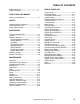
TABLE OF CONTENTS Machine Data Log..........................................2 Table of Contents ...........................................3 HOW TO USE THIS MANUAL How to use this Manual..................................1-1 SAFETY Important Safety Instructions.........................2-1 Hazard Intensity Level. ..................................2-2 Safety Label Location.....................................2-3 OPERATIONS Technical Specifications................................3-1 Controls ................
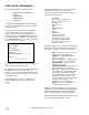
HOW TO USE THIS MANUAL This manual contains the following sections: - - HOW TO USE THIS MANUAL SAFETY OPERATIONS MAINTENANCE PARTS LIST The HOW TO USE THIS MANUAL section will tell you how to find important information for ordering correct repair parts. Parts may be ordered from authorized Windsor dealers. When placing an order for parts, the machine model and machine serial number are important. Refer to the MACHINE DATA box which is filled out during the installation of your machine.
IMPORTANT SAFETY INSTRUCTIONS When using a gas or diesel powered appliance, basic precaution must always be followed, including the following: READ ALL INSTRUCTIONS BEFORE USING THIS MACHINE. ! WARNING: To reduce the risk of fire, electric shock, or injury: This machine is for dry use only and shall not be used or stored outdoors in wet conditions. Use only as described in this manual. Use only manufacturer’s recommended brushes and attachments.
HAZARD INTENSITY LEVEL The following symbols are used throughout this guide as indicated in their descriptions: HAZARD INTENSITY LEVEL There are three levels of hazard intensity identified by signal words -WARNING and CAUTION and FOR SAFETY . The level of hazard intensity is determined by the following definitions: ! WARNING WARNING - Hazards or unsafe practices which COULD result in severe personal injury or death.
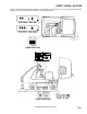
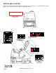
SAFETY LABEL LOCATION NOTE: These drawings indicate the location of safety labels on the Tracer FS. If, at any time, the labels become illegible contact your Windsor representative for prompt replacement.
SAFETY LABEL LOCATION NOTE: These drawings indicate the location of safety labels on the Tracer FS. If, at any time, the labels become illegible contact your Windsor representative for prompt replacement.
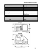
TECHNICAL SPECIFICATIONS ITEM Power Source: Gas Diesel Suspension Maximum Speed Sweep Path Main Broom Main Broom Diameter Side Broom Hopper Capacity Hopper Dump Dust Control Brakes Steering Tires Dimensions: Height Weight Length Coverage DIMENSION/CAPACITY 20hp, 2 Cylinder, Liquid-Cooled 14hp, 2 Cylinder, Liquid-Cooled Floating I-Beam 10k/hour 1200mm 812mm 355mm 510mm 180 liters 1520mm 54ft2 (5m 2) pleated filter with exclusive cyclonic pre-filter Dual mechanical disc with parking brake Rear wheel, rack &
CONTROLS SPECIAL NOTES: The sound pressure level at the operator’s ear was measured to be 78 dBA for the QTFSG and 83 dBA for the QTFSD. This was a nearfield, broad-band measurement made during normal operation on a composite tile floor with a white pad. This appliance contains no possible source of impact noise. The instantaneous sound pressure level is below 63 Pa. 3-2 The weighted root mean square acceleration at the 2 operator’s arms was measured to be below 2.5m/s for 2 the QTFSG and below 3.
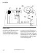
CONTROLS A. Directional Control Pedal B. Brake Pedal C. Parking Brake D. Operator Seat E. Rear Cover Latch F. Main Broom Lever G. Side Broom Lever H. Filter Shaker Switch I. Hopper Door Switch J. Hopper Lift Switch K. Hopper Safety Arm L. Engine Temperature Light M. Oil Pressure Light N. Engine Glow Plug Light (Diesel Only) O. Light Switch P. Engine Throttle Handle Q. Choke Cable R. Key Switch S. Circuit Breakers T. Horn Pad U. Steering Wheel V.
CONTROLS A - DIRECTIONAL CONTROL PEDAL E – REAR COVER LATCH This pedal controls the direction of travel and the speed of the machine. The rear cover latch locks the rear cover in the closed position. To open the rear cover, push the latch in and pull the rear cover back. To close the rear cover, lower it slowly until the latch engages the floor slot. Do not let the rear cover drop, or damage to the latch or cover may occur.
CONTROLS I – HOPPER DOOR SWITCH L – ENGINE TEMPERATURE LIGHT The hopper door switch opens and closes the hopper dump door. Pushing the front half of the hopper door switch closes the hopper dump door. Pushing the rear half of the switch opens the hopper dump door. A beeper sounds when the door is in the closed position. Sweeping should not be attempted when the hopper door is closed. The engine temperature light indicates when the engine is overheating.
CONTROLS Q – CHOKE (GAS ONLY) DIESEL: DEVICE By pulling this knob out, the choke is engaged for cold starting. To release choke, push the knob in. RATING CB-1 CB-2 30A 30A CB-3 15A CB-4 CB-5 15A 15A R – KEY SWITCH The key switch controls starting and electrical power for most machine functions. To start the machine, turn the key clockwise past the “RUN” position to the crank position. After engine has started release key. (For starting diesel engines, see “Glow Plug Light”).
OPERATIONS BEFORE OPERATING THE FS: TO SWEEP 1. Complete the machine data sheet on page 2. 2. Read this manual carefully before operating or servicing the machine. Plan the sweeping pattern in advance. For efficient operation, the sweeping runs should be long with as little stopping and starting as possible. Overlap the brush paths and complete an entire section at one time. Do not operate machine unless Operation manual is read and understood. 3. 4.
OPERATIONS STOPPING THE MACHINE 1. 2. TO ENGAGE THE HOPPER SAFETY ARM Remove foot from the directional pedal and apply the brake. Raised hopper may fail. Engage hopper safety arm before working under hopper. Raise and turn off the brooms by pulling the main and side broom levers back to the rear locked position. 1. 3. Set the parking brake. FOR SAFETY: Before leaving or servicing machine; stop on level surface, set parking brake, turn OFF machine and remove key. 4.
OPERATIONS TO DISENGAGE THE HOPPER SAFETY ARM TO JACK UP MACHINE 1. 2. 1. 2. 3. Raise the hopper. Place the safety arm in its storage position on the inside of the hopper lift arm. Lower the hopper. Empty and lower the hopper. Turn the key switch off and set the parking brake. FOR SAFETY: Before leaving or servicing machine; stop on level surface, set parking brake, turn off machine and remove key. 3. Block the tires that are not being raised to prevent the machine from rolling.
MAINTENANCE HYDRAULIC FLUID 5. 6. Hydraulic fluid is used with the hydraulic pump to operate the hopper lift system and the side broom motor. The condition of the hydraulic fluid plays a large part in determining the life of the hydraulic system. The hydraulic fluid used in the Tracer Gas/Diesel powered Floor Sweeper is Chevron 400 15W40. If a different hydraulic fluid is used, it must closely match the viscosity specification below. Remove bolts (4) in feet of reservoir.
MAINTENANCE HYDRAULIC FILTER The hydraulic filter keeps the machines hydraulic system clean to a level of 10 microns. The hydraulic fluid filter is located just inside the left rear frame. The filter should be changed every 500 hours. TO 1. 2. 3. 4. 5. 6. 7. 8. REPLACE FILTER ELEMENT: Stop the engine and set the parking brake. Open the seat support. Unthread and discard the hydraulic fluid filter element. Apply a thin coat of hydraulic fluid to the seal of the new hydraulic fluid filter element.
MAINTENANCE MAIN BROOM (Refer to the Main Broom Group and Main Broom Lift Group in the Parts section) TO INSTALL THE MAIN BROOM 1. Turn off machine and set parking brake. FOR SAFETY: The main broom and the vacuum impeller automatically begin to operate when the main broom lever is positioned in the forward end of its slot. FOR SAFETY: Before leaving or servicing the machine, stop on level surface, apply parking brake, turn off machine and remove key.
MAINTENANCE CHECKING AND ADJUSTING THE MAIN BROOM PATTERN 1. 2. 3. 4. 5. 6. 7. 8. 9. Using chalk, or similar material, coat and area of the floor that is flat and smooth. If a suitable material is not available, run the broom for two minutes during the following test. With the main broom raised, position the machine so that the main broom is directly over the chalked area. Apply the parking brake to prevent the machine from moving. Lower the main broom to the floor for 10-15 seconds.
MAINTENANCE 5. SIDE BROOM (Refer to the Side Broom Group in the Parts section) FOR SAFETY: The side broom automatically begins to operate when the side broom lever is positioned in the forward end of its slot. The side broom is used to clean debris sway from curbs and walls, and sweep it into the path of the main broom. Inspect the side broom daily for wear or damage. Remove any string, wire or banding found wrapped around the side broom, side broom hub, or shaft. 6. 7.
MAINTENANCE TRANSMISSION JACKSHAFT BELT ADJUSTING THE JACKSHAFT BELT The transmission belt transfers power from the engine to the transmission jackshaft on the gasoline machines and from the engine jackshaft to the transmission jackshaft on the diesel powered machines. Proper alignment is important for all belts on Tracer machines. To properly align the transmission jackshaft belt: Repeat Steps 1-8 from above then: 9. TO REPLACE BELT 10. 1. Turn off machine and set parking brake.
MAINTENANCE TO ALIGN BELT VACUUM IMPELLER BELT (Refer to the Impeller Group in the Parts section) 1. 8. Repeat steps 1-7 Loosen tension on impeller drive pulley on end of transmission jackshaft. 9. Slide pulley side to side on shaft to make proper alignment. 10. Retighten setscrews in pulley. 11. Reverse Steps 1 –7. MAIN BROOM BELT (Refer to Main Broom Group in the Parts section) The main broom belt transfers power from the rear jackshaft to the main broom pulley.
MAINTENANCE IMPELLER BELT 6. The impeller belt transfers power from transmission jackshaft to impeller. 7. 8. 1. Turn off machine and set parking brake. FOR SAFETY: Before leaving or servicing machine, stop on level surface, apply parking brake, turn off machine and remove key. 2. 3. 4. 5. 6. 7. 8. 9. Raise rear cover. Disconnect batteries from machine. Remove the belt guard cover. Release tension on impeller belt using tension bolt under impeller arm.
MAINTENANCE DRIVE WHEEL CHAIN (Refer to the Front Wheel Group in the Parts section) REPLACING THE RIGHT BROOM DOOR SKIRT 1. Turn off machine and set parking brake. The drive wheel chain transfers power from the differential shaft to the drive wheels. Check the chain condition and tension every 200 hours of operation. FOR SAFETY: Before leaving or servicing machine, stop on level surface, apply parking brake, turn off machine and remove key. REPLACING AND ADJUSTING THE DRIVE WHEEL CHAINS 2. 3. 1.
MAINTENANCE REPLACING THE LEFT BROOM SKIRT ADJUSTING THE REAR BROOM SKIRT 1. Turn off machine and set parking brake. 1. FOR SAFETY: Before leaving or servicing machine, stop on level surface, apply parking brake, turn off machine and remove key. FOR SAFETY: Before leaving or servicing machine, stop on level surface, apply parking brake, turn off machine and remove key. 2. 2. 3. Raise rear cover and disconnect the batteries from the machine. Open the left broom door.
MAINTENANCE HOPPER SEALS The hopper seals prevent dust from exiting around the hopper where it meets the broom chamber. There are two side hopper seals and one upper hopper seal. These seals should be inspected for wear or damage daily. When correctly adjusted, the two hopper side seals should clear the floor by 0 to 1/8 inch (0 to 3mm). REPLACING THE HOPPER SEALS 1. 2. Park the machine on a smooth, level floor. Raise the hopper and engage the hopper safety arm. Raised hopper may fall.
MAINTENANCE HOPPER DOOR SEALS 4. The hopper door seals prevent debris from spilling out of the hopper before dumping. There are two hopper door side seals, one hopper door lower seal and one hopper door upper seal. The upper seal can only be replaced by removing the hopper door from the hopper. The hopper door seals should be inspected for wear or damage daily. They do not require adjustment. 5. Check the distance from the lower rear edge of the hopper to the floor.
MAINTENANCE To clean the filter after removal, use one of the following methods: 1. TAPPING Tap the filter frame gently on the dirty side of the filter down. Be careful not to dent the filter frame. 2. AIR Blow compressed air through the filter opposite the direction of the arrow on the side of the filter. This may be done with filter in the machine. Wear eye and dust inhalation protection when using compressed air. 3. WATER The filter can be soaked in water and mild detergent.
MAINTENANCE BATTERY BATTERY MAINTENANCE The battery provides the power to start the machine. The battery requires regular maintenance to keep them operating at peak efficiency. To get the greatest life from the battery charge it when their charge level reaches 25%of a full charge. Use a hydrometer to check the charge level. Do not allow the battery to remain in a discharged condition for any length of time. Never expose a discharged battery to temperatures below freezing.
HYDRAULIC SCHEMATIC HYDRAULIC TROUBLESHOOTING PROBLEM Hopper will not lift Hopper will not lower 4-15 CAUSE SOLUTION Loss of power to rocker switch Low hydraulic fluid Hopper overloaded Rocker switch failure Speed control orifice plugged Pump solenoid failure Check valve failure Lift cylinder failure Gear pump failure Loss of power to rocker switch Rocker switch failure Speed control orifice plugged Check valve failure Key switch must be on check circuit breaker Add hydraulic fluid Empty hopper Test
PROPEL SYSTEM TROUBLESHOOTING PROBLEM.
MACHINE TROUBLESHOOTING PROBLEM. Excessive dusting Poor sweeping performance Machine travels slowly or not at all CAUSE SOLUTION Dust skirts and seals worn, damaged, not adjusted properly Dust filter clogged or damaged Vacuum hose damaged Vacuum fan not operated Broom bristles worn Replace or adjust skirts or seals. Brooms not adjusted properly. Debris caught in broom drive mechanism. Main broom drive failure Side broom drive failure Adjust brooms.
MAINTENANCE SERVICE SCHEDULE MAINTENANCE Check and add fuel (see Engine’s Owner’s Manual supplied) Check and add engine oil (see Engine’s Owner’s Manual supplied) Check for fuel, oil and coolant leakage (see Engine’s Owner’s Manual supplied) Check radiator for dust and insects (see Engine’s Owner’s Manual supplied) Check water level of batteries after charging Check main broom & side broom adjustment, remove string, etc – check for damage Check main broom skirts and seals Check hopper lip skirts for damage