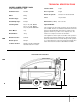
OWNER’S GUIDE Operating Instructions (GB/USA) Instrucciones de Manejo (ESP) Mode d’emploi (FR) Bedienungsanweisung (GER) Mode de Emploi (ITA) MODELS COVERED IN THIS GUIDE: SABER MODEL TYPE POWER SOURCE S28 S34 S34SP 28” Disc 34” Disc 34” Cylindrical Head 36V Battery 36V Battery 36V Battery MODEL TYPE POWER SOURCE QQS28 QQS34 QQS34SP 28” Disc 34” Disc 34” Cylindrical Head 36V Battery 36V Battery 36V Battery STRIDE II IPX4 Read these instructions before operating the machine Antes de usar la m
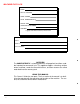
MACHINE DATA LOG MODEL DATE OF PURCHASE SERIAL NUMBER SALES REPRESENTATIVE # DEALER NAME OPERATIONS GUIDE NUMBER PUBLISHED Copyright 1995 Windsor Industries, Printed in USA YOUR DEALER Name: Address: Phone Number: For the name and address of your dealer contact: Windsor Ind. OVERVIEW The SABER/STRIDE II is a battery powered, self propelled, hard floor scrubber intended for commercial use.
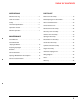
TABLE OF CONTENTS OPERATIONS PARTS LIST Machine Data Log . . . . . . . . . . . . . . . . . . . . . . . . 2 Main Frame Assembly. . . . . . . . . . . . . . . . . . . . . . 18 Table of Contents . . . . . . . . . . . . . . . . . . . . . . . . . 3 Brake/Squeegee Lift Assemblies. . . . . . . . . . . . . . 20 Safety . . . . . . . . . . . . . . . . . . . . . . . . . . . . . . . . . . 4 Rear Panel Mechanical . . . . . . . . . . . . . . . . . . . . . 22 Technical Specifications . . . . . . . . . . . . . . .
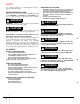
SAFETY The following symbols are used throughout this guide as indicated in their descriptions: WHEN SERVICING MACHINE: HAZARD INTENSITY LEVEL • • • There are three levels of hazard intensity identified by signal words -WARNING and CAUTION and FOR SAFETY. The level of hazard intensity is determined by the following definitions: ! WARNING WARNING - Hazards or unsafe practices which COULD • • • Avoid moving parts. Do not wear loose clothing; jackets, shirts, or sleeves when working on the machine.
TECHNICAL SPECIFICATIONS MODEL:SABER/STRIDE II 28/34 Year of Construction: 1998 Solution Tank: 33 gal. Nominal Power: 2.88 kW Recovery Tank: 33 gal.
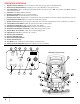
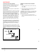
OPERATION CONTROLS 1. 2. Squeegee /Vacuum Switches. Turns on and off the vacuum and squeegee system seperately if desired. Brush Pressure Indicator/Switch. Sets brush pressure on floor with LED’s to show pressure level. 3. 4. One Touch Switch. Activates scrubbing and vacuuming functions. Pressing once turns “ON”. Pressing twice turns “OFF” scrubbing and vacuuming functions. Key Switch. Turns ON and OFF the machine. 5. Emergency Stop Switch. Cuts off power to the machine. 6. 7. Speed Control Lever.
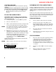
MACHINE OPERATION STARTING MACHINE SCRUBBING WITH THE SABER/STRIDE II NOTE: Perform pre-run machine check before operating machine. FOR SAFETY: Before starting machine, make sure that all safety devices are in place and operating properly. 1. Turn the key switch clockwise to the “ON” position. Move the directional control lever in the desired direction. Plan the scrubbing pattern in advance. The longest track is around the perimeter of the area to be cleaned.
MACHINE OPERATION DOUBLE SCRUB Floors which are heavily soiled or have thick accumulations of floor finish may not clean sufficiently with one pass. In these cases it will be necessary to double scrub. To double scrub, begin scrubbing as usual, but after pushing number 1, press the squeegee button to turn off vac motor. Manually raise the squeegee. Make the first pass over the surface being cleaned with the solution on, and brushes down and squeegee up.
MAINTENANCE SCRUB BRUSHES NOTE: All original equipment brushes are equipped with “Perform Alert ©. This feature will tell the operator when it is time to replace the scrub brushes. “Perform Alert © brushes have bright yellow tufts located on these tufts are pre-trimmed to indicate the length of a worn out brush. When the tufts in the scrub brush wear to a length equal to the yellow tufts, the scrub brushes should be replaced.
MAINTENANCE SCRUB DECK SKIRT AND SQUEEGEE The skirts and squeegee should be inspected for wear and damage. The skirt is self adjusting. Replace skirt when they become cracked, worn, torn or brittle. TO REPLACE OR ROTATE REAR SQUEEGEE BLADES 1. With the squeegee in the up position, turn the key switch “OFF”. 2. Remove the squeegee from the machine. Unlatch and remove blade retainer strap and remove squeegee blade assembly.
MAINTENANCE ADJUSTING SQUEEGEE Adjusting the squeegee is a two part process. First, the squeegee tool must have correct pitch in order for the squeegee blade to have the same deflection at each tip as well as the center. The pitch adjustment on the SABER/STRIDE II is facilitated by the use of a spirit level mounted on the squeegee tool. The second adjustment is the amount of deflection or down pressure on the squeegee.
BATTERIES The batteries provide the power to operate the machine. The standard are four 6 volt batteries rated at 250 A/h at a 6-hour rate. The batteries require regular maintenance to keep them operating at peak efficiency. 3. 4. The machine batteries will hold their charge for long periods of time, but they can only be charged a certain number of times. To get the greatest life from the batteries, charge them when their charge level reaches 25% of a full charge.
BATTERIES TO CHARGE THE BATTERIES ! CAUTION When servicing machine, avoid contact with battery acid. ! WARNING Batteries emit hydrogen gas. Explosion or fire can result. Keep sparks and open flame away. Keep covers open when charging. ! WARNING Wear eye protection and protective clothing when working with batteries. ! WARNING Charge batteries in a well ventilated area. Leave the solution tank open.
SERVICE SCHEDULE Before Starting the Work Period Maintenance Item Daily Check Battery water level * Check Vac Hose Connections * Clean the Squeegee Blades * Inspect Brushes or Pads for debris ie: wire, string, wear * Inspect Vac fan shut off float screen * End of Work Drain & Rinse Tanks Period Raise Squeegee Assembly Before Raise Scrub Deck Assembly Storing Weekly Annually * * * Charge the Batteries * Remove the Pad Drivers/Brushes * Check the Brushes/Padsfor Damage and or wear * Cl
SQUEEGEE BLADE/BRUSH HEAD OPTIONS SQUEEGEE BLADE OPTIONS P/N 73932 73934 82529 82528 82638 82637 82641 82640 73935 73900 73902 73901 73936 73937 73925 73922 73926 73923 73927 73924 Desc.
SERVICE LOCATION DETAILS BRUSH HEAD MODELS: S28, S34, QQS28, QQS34 ALL MODELS 1 2 SQUEEGEE ASSEMBLY 3 4 REAR ELECTRICAL CONTROL PANEL 6 (REF.
SERVICE LOCATION PARTS LIST Ref 1 2 3 4 5 6 7 Part No. Qty 70532 80657 87029 48012 82191 27756 27770 6 1 2 2 1 1 1 Serial No. Description From SCR, 10-32 X 1/2 PPHMS BLK PIN, COTTER HAIR .148" DIA X 3/4 WASHER, 5/16 FLAT SS KNOB, 5/16-18 4 PRONG PIN, COTTER HAIR .