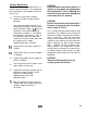
IMPORTANT SAFETY INSTRUCTIONS When using an electrical appliance, basic precaution must always be followed, including the following: READ ALL INSTRUCTIONS BEFORE USING THIS MACHINE. This machine is for commercial use. 1. Use only as described in this manual. Use only manufacturer’s recommended attachments. 2. Use indoors only. Do not use outdoors and do not expose to rain. 3. Machine can cause a fire when operating near flammable vapors or materials.
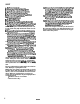
THIS PRODUCT IS FOR COMMERCIAL USE ONLY. ELECTRICAL: In the USA this machine operates on a standard 15 amp 115 volt A.C. power circuit (12OV nominal). Special voltage models are available for international applications. The amp, hertz and voltage are listed on the data label found on each machine. Using voltages above or below those indicated on the data label will cause serious damage to the motors.
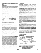
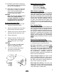
CONTROLS Solution Power Cord Vat intake Filter/Screen\ Main Handle Adjust brush to proper cleaning position by using lever located on the front of the frame. Start at No. 1 “new brush” (black) position. If more carpet pile agitation is desired, lower brush setting one position at a time. (See fig. 1 below) Fig.
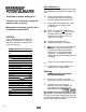
Preparing the SPIRIT DUAL: Filling Solution Tank: For Hard Floor: 1.) Install the optional kit : Vac Shoe Squeegee (p/n 02285). Raise the SPD vac shoe and place the squeegee assembly over the vac shoe intake. Center the squeegee on the vac shoe and secure by tightening the two retaining knobs. 1.) Set dome and recovery tank to the side. 2.) Use a clean bucket to fill the solution tank with hot water.
SPIRIT 14. When solution tank empties the machine will start streaking and won’t completely clean the floor. Turn both switches off, empty the recovery tank, and refill the solution tank. Use the clear drain hose on the rear of the solution tank as a sight gage to determine amount of fluid in tank. 15. Ventilate the room when cleaning has been completed. Keep all traffic off the floor until it is thoroughly dry. 1. Fill the solution tank. 2. Move machine to the cleaning area. 3.
Approved Accessory Tools: 15.) Ventilate the room when cleaning has been completed. Keep all traffic off the floor until it is thoroughly dry. Standard Floor Wands (SFW, SW, or SW-PRO) Deluxe Hand Tool (DHT) Upholstery Hand Tool (UPH3) 16.) When done cleaning for the day bring the machine to a utility sink and floor drain. Perform the daily/regular maintenance. Set the recovery tank aside so solution tank will dry. CAUTION: When not using the machine put the brush in the storage position.
Dailv Maintenance: WARNING OF POTENTIAL INJURY These procedures are followed at the end of each work period to extend the life of the machine. This product contains moving parts. To reduce the risk of injury; unplug the machine before servicing. 1.) Empty unused cleaning solution by disconnecting clear hose on back of machine and pouring into floor drain. 2.) Inspect and clean solution filter screen inside tank and vac intake screen inside dome. 3.) Flush the system.
Periodic Maintenance: These procedures are performed by a trained service technician. The regularity of these procedures may depend on the machine's use. 1.) Flush the system with a special solution to reduce scaling (alkaline build-up). Use acetic acid (white vinegar) or an anti-browning solution. Mix one quart acetic acid with 2 gallons (I:8 liters) of hot water in the solution tank (if an anti-browning solution is used follow manufacturer’s instructions).
Troubleshooting- Chart Condition Corrective Action No Power To Machine: Dead electrical circuit breaker in fuse box Check building circuit breaker. Faulty power cord Replace Power switch failure Test switch for continuity/Replace if necessary. Faulty circuit breaker Test circuit breaker for continuity/Replace if necessary. Internal wiring problem With the machine unplugged, check for, and correct, any loose wire connections inside the machine at the switches and terminal block.
Troubleshooting Chart Condition Corrective Action Accessory Tool Fitting Difficult to Connect: Corrosion on fitting Clean with steel wool. Remove and soak in acetic acid (white vinegar). Lubricate lightly with silicone base lubricant. Floor Not Getting Clean: Severe soil conditions Make several passes at right angles to each other. Use a prespray. Floor Too Wet: Worn spray jet(s) Replace spray jets which are producing more than a fine mist.
Servicing the Vac Motor To access the vac motor first remove the solution tank. There are (2) screws which attach the vac motor mounting bracket to the chassis. Loosen the clamp to remove the hose. To replace the motor assembly it will be necessary to remove the (3) screws which attach the motor to the vac motor mounting bracket. See page 18 for the complete vac motor and mounting equipment parts list. Wire Important: These brushes wear quicker as the length shortens due to increased heat.
6 Vac Shoe Assembly Assembly Reverse 10 11 57047 87074 05016 73181 70190 70057 89061 87008 87016 70088 Nut, l/4-20 Nylock Washer, 3/8 ID x .OlO Wave Arm, Vac Shoe Parallel Spacer, .259 ID x .38x .25 Scr, l/4-20 x 1/2 BHCS Scr, l/4-20 x 1 .O PHMS Weight, Vat shoe Washer.
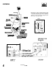
RECOVERY & SOLUTION TANKS RECOVERY TANK Each tank has a filter screen which protects the machine’s internal parts from damage. Ensure that these screens are in place and clean before operating the machine.
RECOVERY & TANK ASSEMBLY Parts List RECOVERY TANK PARTS LIST; 2 3 4 5 6 7 8 9 10 11 12 13 14 87013 73280 38088 75078 14042 39343 39411 27079 27508 27354 28033 50775 50776 Washer, l/4 Flat Spacer, 1/4 ID x 3/8 Nylon Handle, Recovery Tank Tank, Recovery Bushing, 1.63 ID Snap Hose, 1.5 x 34” Vac Hose, 1.5 x 52” Vac Cuff, White 1.
Pump...Manifold...VaIve Spray Jets Rinse in hot water or use compressed air to clean. Nozzles can also be soaked in an acetic acid solution (white vinegar). CAUTION: Do not use pins or wires to clean or unclog jets. Using wires or pins to unclog jets may ruin spray pattern. 6 ‘23 24 26 Replace jets that no longer produce a fine mist spray or over saturate carpet.
Pump...Manifold...VaIve 04008 56023 78156 56014 65154 12 13 14 15 16 17 18 19 20 24 25 26 27 28 29 31 32 33 70253 57081 40033 27665 70088 84134 31016 40038 20042 39452 70114 14523 39330 44061 44052 54094 66095 57018 73426 87025 70085 39364 57104 87016 56048 Adaptor, .1/4 MPT x l/4 FPT Nipple, l/4 MPT x 1.5 Tee, l/4 FPT Nipple, l/4 Close Pump, 115V 50 PSI OPEN Screw, 10-32 x 1.
HANDLE...CHASSIS...
HANDLE,..CHASSIS...SWITCHES 2 3 4 5 6 7 8 9 10 11 12 13 14 15 16 17 18 19 20 21 22 23 24 25 26 27 28 29 30 31 32 33 34 35 36 37 38 39 40 41 42 43 44 45 46 57104 Open 89114 41236 70249 73636 73596 51193 38269 41302 57047 36123 41144 70361 57238 51251 27561 27699 27371 57113 70105 87030 70272 50498 72147 62322 57028 27376 70406 73169 50638 70066 87016 27711 70434 23572 70537 57234 57138 99817 50182 35229 62755 35198 35228 Nut, 10-32 w/Star Washer Wheel, 10” Hub Cap, Y8” Shaft Scr, l/4-20 x 1.
BRUSH DRIVE ASSEMBLY To access the belt remove the belt cover. To replace the belt it is necessary to loosen the motor and remove the brush. The “preset” belt tension is correct when the motor and belt are securely back in place. Check pulley alignment and correct if necessary. The brush pulley and motor pulley can be aligned using a straight edge. Ensure that both protective covers are back in place before operating the machine.
BRUSH DRIVE ASSEMBLY Parts List 2 3 4 09019 70078 03089 5A 140080 5B 140081 5c 140156 6 87146 36166 7 8 70190 73181 9 70201 10 11 41296 12 70011 87025 13 14 70020 15 67005 66094 16 17 57123 19A 53093 19B 53173 20 87018 21 70074 22 6407 1 23 36044 24 70363 25 11031 26 57047 27 36050 28 70434 29 36043 30 87013 31 70015 32 64088 33 67094 34 70497 35 29157 36 73767 37 48063 38 27666 39 70562 40 57016 41 70118 42A 140174 42B 140086 42C 140157 Bearing, Brush Shoulder bolt, 5/16 OD x 3/8 L Axle, Pulley Brush,
Vac Motor Assemblv Roller Front of frame 22
Vac Motor Roller Assembly 1 2 3 4 5 6 7 8 9 10 11 12 13 14 15 57022 57085 03027 67082 70018 73178 140077 87030 87013 57047 66073 51247 73040 70363 62397 Nut.
SPIRIT DUAL Squeegee Assembly To attach to the SPIRIT DUAL... Raise the SPD vac shoe and install squeegee assembly over the vac shoe intake. Center the squeegee on the vac shoe and secure by tightening the two retaining knobs.
115V SPR WIRING DIAGRAM 98353 7/1/97 25
LIMITED WARRANTY Windsor Industries, Inc. warrants new machines against defects in material and workmanship under normal use and service to the original purchaser. The warranty period is subject to the conditions stated below. 3 YEARS FOR PARTS AND I YEAR FOR SERVICE LABOR Exceptions: Rotationally molded polyethylene tanks carry a 6 year parts and 1 year service labor warranty. VERSAMATK models carry a 3 year warranty on brush motors, vacuum motors, and belts, and a 1 year service labor warranty.