WALK BEHIND SCRUBBER Operating Instructions (ENG) Bedienungsanleitung (GER) Istruzioni operative (ITA) Instrucciones de funcionamiento (SPA) Manuel d’utilisation (FRE) MODELS: SCEX264 10052320 SCEOX264 10052290 SCEX324 10052330 SCEOX324 10052300 IPX4 Read these instructions before using the machine Bitte lesen Sie diese Anleitungen, bevor Sie die Maschine in Gebrauch nehmen Leggere attentamente queste istruzioni prima di azionare la macchina Lea las instrucciones antes de utilizar la máquina Lire ce
MACHINE DATA LOG/OVERVIEW MODEL _______________________________________ DATE OF PURCHASE __________________________ SERIAL NUMBER ______________________________ SALES REPRESENTATIVE # _____________________ DEALER NAME ________________________________ OPERATIONS GUIDE NUMBER ___________________ PUBLISHED __________________________________________ YOUR DEALER Name: __________________________________________________________________________________________________ Address: _____________________________________
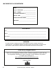
TABLE OF CONTENTS Machine Data Log/Overview.........................2 Table of Contents..........................................3 HOW TO USE THIS MANUAL Vacuum Motors................................. .........4-11 Actuator Scrub Deck......................... .........4-12 Greasing Axles ................................. .........4-13 Machine Troubleshooting ................. .........4-14 How to use this Manual.................................1-1 GROUP PARTS LIST SAFETY Control Handle................
HOW TO USE THIS MANUAL This manual contains the following sections: - - HOW TO USE THIS MANUAL SAFETY OPERATIONS MAINTENANCE PARTS LIST The HOW TO USE THIS MANUAL section will tell you how to find important information for ordering correct repair parts. Parts may be ordered from authorized Windsor dealers. When placing an order for parts, the machine model and machine serial number are important. Refer to the MACHINE DATA box which is filled out during the installation of your machine.
IMPORTANT SAFETY INSTRUCTIONS When using an battery powered appliance, basic precaution must always be followed, including the following: READ ALL INSTRUCTIONS BEFORE USING THIS MACHINE. ! WARNING: To reduce the risk of fire, electric shock, or injury: Use only indoors. Do not use outdoors or expose to rain. Use only as described in this manual. Use only manufacturer’s recommended components and attachments.
HAZARD INTENSITY LEVEL The following symbols are used throughout this guide as indicated in their descriptions: HAZARD INTENSITY LEVEL There are three levels of hazard intensity identified by signal words -WARNING and CAUTION and FOR SAFETY. The level of hazard intensity is determined by the following definitions: ! WARNING WARNING - Hazards or unsafe practices which COULD result in severe personal injury or death.
SAFETY LABEL LOCATION NOTE: These drawings indicate the location of safety labels on the machine. If at any time the labels become illegible, promptly replace them. SAFETY DECAL 86252530 PRV NO. 81494 BATTERY CAUTION 86252520 PRV NO. 80885 CIRCUIT BREAKER DECAL 86243530 PRV NO.
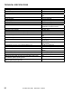
TECHNICAL SPECIFICATIONS ITEM Nominal power Rated Voltage Rated Amperage Batteries Scrub Brush Motors Vacuum Motor Propelling Motor Mass (GVW) Weight empty without batteries Solution Control Solution tank capacity Recovery tank capacity Scrub brush diameter for 26 in. (66 cm) scrub head Scrub brush diameter for 32 in.
TECHNICAL SPECIFICATIONS ITEM Height Length with 26 in. (66 cm) scrub head Length with 32 in. (81 cm) scrub head Width without squeegee and scrub head Width of squeegee for 26 in. (66 cm) scrub head Width of squeegee for 32 in. (81 cm) scrub head Width of scrub path for 26 in. (66 cm) scrub head Width of scrub path for 32 in. (81 cm) scrub head MEASURE 45 in. (114 cm) 64 in. (163 cm) 66 in. (167 cm) 24 in. (61 cm) 35 in. (89 cm) 39 in. (99 cm) 26 in. (66 cm) 32 in.
HOW THE MACHINE WORKS The Saber Cutter is a battery powered, selfpropelled, hard floor scrubber intended for commercial use. The appliance applies a cleaning solution onto a hard floor, scrubs the floor with brushes, and then vacuums the soiled water back into the recovery tank. The machine's primary systems are the solution system, scrub system, recovery system, and directional control system. The function of the solution system is to store cleaning solution and deliver it to the scrub system.
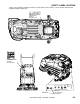
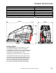
COMPONENTS 12 14 7 3 1 2 6 11 9 5 15 13 4 8 10 1. Control Panel 2. Front Cover 3. Recovery Tank 4. Recovery Tank Drain Hose 5. Scrub Head Shrouds 6. Solution Tank 7. Solution Tank Cover 8. Solution Tank Drain Hose 9. Solution Strainer 10. Squeegee 11. Aqua-Mizer 12. Top Cover 13. Vacuum Motor 14. Recovery Tank Dome 15.
CONTROLS 2 13 5 3 6 9 8 7 16 15 1 4 10 14 12 11 3-5 CUTTER 24V (SCE) 86037020 04/04/07
CONTROLS 1. 2. 3. 4. 5. 6. 7. 8. Key Switch Emergency Shut Off Switch Speed Control Knob Propel Control Lever Reverse Button Brush Switch Actuator Switch Solution Control Knob 1. KEY SWITCH Controls the power for machine functions. 9. Vacuum Switch 10. Squeegee Lift Lever 11. Squeegee Pitch Adjustment Knob 12. Squeegee Deflection Adjustment Knobs 13. Battery Charge Level Indicator 14. Parking Brake 15. Hour Meter 16. Brush Pressure Indicator 4.
CONTROLS 7. ACTUATOR SWITCH Adjusts the amount of brush pressure to the floor by raising or lowering the scrub deck. To increase brush pressure, press the bottom of the switch. To decrease brush pressure or rise the scrub deck, press the top of the switch. 10. SQUEEGEE LIFT LEVER Raises and lowers the squeegee. To lower the squeegee, lift the lever from its raised position. To raise the squeegee, lift the lever from its lowered position. 11. SQUEEGEE PITCH ADJUSTMENT KNOB 8.
CONTROLS 13. BATTERY CHARGE LEVEL INDICATOR Indicates the charge level of the batteries. The meter display is divided into 10 vertical bars. Bar illuminated on the far right indicate full charge. Bars flashing near the left side indicate the batteries should be recharged. Further operation of the machine could damage the machine or the batteries. When the machine is left overnight with less than a full charge, the display may initially indicate a full charge.
MACHINE OPERATION PRE-RUN MACHINE INSPECTION FILLING SOLUTION TANK Do a pre-run inspection to find possible problems that could cause poor performance or lost time from breakdown. Follow the same procedure each time to avoid missing steps. NOTE: See maintenance section for pre-run machine inspection checklist items. FOR SAFETY: Before leaving or servicing machine; stop on level surface, turn off machine and remove key. 1. Turn the machine power off. 2.
MACHINE OPERATION NORMAL SCRUBBING TO BEGIN SCRUBBING Plan the scrubbing pattern in advance. The longest track is around the perimeter of the area to be cleaned. For efficient operation, the runs should be the longest possible without turning, stopping, or raising and lowering scrub deck/squeegee. NOTE: In order to achieve the best possible results, the area which is to be cleaned should be swept before scrubbing. Large debris, strings & wire must be removed to prevent being caught in brushes or squeegee.
MACHINE OPERATION RECOVERY TANK DOUBLE SCRUB For floors which are heavily soiled or have thick accumulations of floor finish may not clean sufficiently with one pass. In these cases it will be necessary to double scrub. To double scrub, make the first pass over the surface being cleaned with the squeegee up, vacuum off, the solution on, Aqua-Mizer removed and brushes down. This allows the solution to stay in contact with the soil while loosening the surface accumulation with the brushes.
MAINTENANCE SERVICE SCHEDULE Before starting the work period End of work period before storing MAINTENANCE Check battery acid level Check vac hose connections Clean the squeegee blades Inspect brushes or pads for debris: wire string, wear Inspect vac fan shut off float screen DAILY * * * * MONTHLY ANNUALLY * Drain & rinse tanks * Raise squeegee assembly Raise scrub deck assembly Charge the batteries. Remove the pad drivers/brushes Check the brushes/pads for damage and/or wear Clean squeegee blades.
MAINTENANCE 5 1 12 7 11 9 6 3 8 2 1. Batteries 2. Squeegee 3. Aqua Mizer 4. Scrub Brushes 5. Float Shut-Off 6. Solution Strainer 7. Brush Motor 8. Traction Motor 9. Circuit Breakers 10. Brush Shroud & Brush Skirts 11. Vacuum Motor 12.
MAINTENANCE 1. BATTERIES The batteries provide the power to operate the machine. The batteries require regular maintenance to keep them operating at peak efficiency. The machine batteries will hold their charge for long periods of time, but they can only be charged a certain number of times. To get the greatest life from the batteries, charge them when their charge level reaches 25% of a full charge. Use a hydrometer to check the charge level.
MAINTENANCE TO CHARGE THE BATTERIES CHECKING BATTERY SPECIFIC GRAVITY Use a hydrometer to check the battery specific gravity. ! WARNING When servicing machine, avoid contact with battery acid. ! CAUTION Batteries emit hydrogen gas. Explosion or fire can result. Keep sparks and open flame away. Keep covers open when charging. Battery Check ! WARNING Wear eye protection and protective clothing when working with batteries. ! WARNING CHECKING GRAVITY A. Hydrometer B.
MAINTENANCE 5. Replace the battery caps, and leave them in place while charging. 6. Unplug the battery connector from the machine. CHANGING BATTERIES Stop the machine in a clean area next to the charger. Turn off machine. FOR SAFETY: When charging, connect the charger to the batteries before connecting the charger to the AC wall outlet. Never connect the charger to the AC wall outlet first. Hazardous sparks may result.
MAINTENANCE 2. SQUEEGEE BLADES The front squeegee blade allows solution to pass through channels in the blade into the squeegee assembly while maintaining vacuum to provide lift. The front blade has four wear surfaces and can be rotated for extended life. The front blade should not require regular replacement under normal use. The rear blade wipes the floor to a near dry condition. It is important the rear blade be in good condition to properly do its job.
MAINTENANCE TO ADJUST SQUEEGEE PITCH 1. Choose a smooth, level surface. Turn “ON” the key switch. Lower the squeegee and drive forward at least 2 feet (60cm.). 2. With the squeegee down, stop the machine. Do not allow machine to roll back. FOR SAFETY: Before leaving or servicing the machine; stop on level surface, turn off machine and remove key. 3. Determine the differences, if any, in deflection of the squeegee blade between each end and the middle.
MAINTENANCE 4. SCRUB BRUSHES There are four different types of brushes available to cover applications from cleaning heavily soiled floors to polishing. A pad driver is also available to take advantage of the many cleaning pads on the market. Please refer to the following to assist in selecting the proper brush or pad for the work at hand. UNCOATED FLOORS 1. With the scrub deck up, turn “OFF” the machine.
MAINTENANCE 6. SOLUTION STRAINER The solution strainer is located in front of the left front wheel. The solution strainer protects the solenoid valve from debris. If there is little or no solution flow to the ground, check the strainer for debris. Drain the solution tank and clean the solution strainer. To remove the strainer, turn the bottom part of the strainer counterclockwise until the bottom is separated. Clean out the debris from the wire mesh and re-assemble.
MAINTENANCE 8. TRACTION MOTOR ! WARNING Do not use a pressure washer to clean around the motors. Use tap pressure only. TRACTION MOTOR CARBON BRUSH REPLACEMENT FOR SAFETY: Before leaving or servicing machine, stop on a level surface, turn off machine and remove key. 1. Disconnect batteries from machine. 2. Disconnect the electrical connection to the traction motor. 3. Remove brush cap. 4. Release brush from spring tension. Remove screw connecting brush wire lead to brush holder.
MAINTENANCE 11. VACUUM MOTOR (Refer to the Vacuum Group in the parts section of manual) ! WARNING Do not use a pressure washer to clean around the vacuum motors. Use tap pressure only. Care must be taken so that water is not directed into vacuum motor air intakes. CHANGING VACUUM MOTOR 1. Remove side cover. 2. Disconnect electrical connector to the vacuum motor. 3. Loosen clamp and disconnect hose from vacuum intake. 4. Remove vacuum motor mounting bracket bolts, which are located under frame. 5.
MAINTENANCE 12. ACTUATOR SCRUB DECK REMOVAL/REPLACEMENT FOR SAFETY: Before leaving or servicing machine, stop on a level surface, turn off machine and set parking brake (If option is installed). 1. Remove front cover. 2. Remove the two nuts below the scrub deck that attach the actuator bracket. 3. Remove clevis pin and rue ring from lower bracket of actuator, make sure not allow actuator bracket to rotate. 4. Disconnect actuator from wiring harness. 5.
MAINTENANCE RECOMMENDED GREASING: 1-2 strokes of Mobiltemp®78 or compatible clay-based or calcium-based grease.
MACHINE TROUBLESHOOTING PROBLEM Poor or no water pick-up CAUSE Squeegee out of adjustment SOLUTION Adjust squeegee Debris caught on squeegee Worn squeegee blades Remove debris Rotate or replace squeegee blades Clear obstruction from hose Vacuum hose clogged Vacuum hose disconnected from squeegee or recovery tank Vacuum hose damaged Recovery tank not sealed Foam filling recovery tank Vacuum motor does not run, or runs slowly Recovery tank full Recovery tank float system dirty Circuit breaker tripped L
MACHINE TROUBLESHOOTING PROBLEM Little or no solution flow to the floor No power to machine CAUSE Solution tank empty SOLUTION Fill solution tank Solution flow turned off or set too low Solution strainer plugged Solution hoses obstructed Turn on or increase flow setting Clean solution strainer Clear obstruction from hose Solution solenoid valve obstructed or stuck Vent hole in solution tank lid obstructed Battery disconnected Clean or replace Emergency shut-off activated (If included) Battery connec
CONTROL HANDLE 1 6 3 10 5 2 4 7 8 9 11 5-1 CUTTER 24V (SCE) 86037020 04/04/07
CONTROL HANDLE REF 1 2 3 4 5 6 7 8 9 10 11 PART NO. 86238730 86257230 86254920 86231480 86277070 86240990 86277060 86277050 86238740 86004120 86004130 PRV NO. 38307 730125 730153 140504 70784 41431 70783 70782 38308 38312 38313 QTY 1 2 2 2 2 2 4 4 1 - DESCRIPTION HANDLE, LEFT SWITCH, SPST MOM NO W/LEVER SPRING, COMP .240D X 1.25 X .
COVER (FRONT) & TANK MOUNT 5 8 7 2 3 9 3 2 10 1 6 5-3 CUTTER 24V (SCE) 86037020 04/04/07
COVER (FRONT) & TANK MOUNT REF 1 2 3 4 5 6 7 8 9 10 PART NO. 86070150 86010670 86276780 86062530 86004790 86276380 86278080 86271840 86010670 86068150 PRV NO. 140574 87029 70728 27925 48012 70639 70823 57285 87029 140706 QTY 1 4 4 1 2 2 2 2 2 1 DESCRIPTION BRKT, TANK MOUNT 24V WASHER, 5/16 FLAT SS SCR, 5/16-18 X 3/4 HHCS SS COVER, FRONT, 24V GRY KNOB, 5/16 –18 4 PRONG SCR, 5/16-18 X 1.25 SSSCU SET SCR, 5/16-18 X 1.
COVER (TOP) & TANK MOUNT 1 3 5 7 9 2 3 4 11 8 3 10 5 3 6 5-5 CUTTER 24V (SCE) 86037020 04/12/07
COVER (TOP) & TANK MOUNT REF 1 2 3 4 5 6 7 8 9 10 11 PART NO. 86062540 86271840 86010670 86239630 86276780 86073700 86069630 86233390 86271870 86276490 86292630 86276780 PRV NO.
DECAL 1 7 2 3 4 5 6 5-7 CUTTER 24V (SCE) 86037020 04/04/07
DECAL REF 1 2 3 4 5 6 7 PART NO. 86243560 86243520 86243530 86243600 86243550 86243180 86004970 PRV NO. 500573 500564 500565 500578 500572 500479 50990 QTY 1 1 1 1 1 1 1 DESCRIPTION LABEL, CUTTER RIGHT LABEL, ELEC. PANEL 24V DELUXE LABEL, ELEC. PANEL. LOWER 24V LABEL, SQUEEGEE LEVER LABEL, CUTTER LEFT LABEL, SOLUTION FILL 24V LABEL, WINDSOR LOGO DOMED CUTTER 24V (SCE) 86037020 04/04/07 SERIAL NO.
ELECTRICAL PANEL 1 2 3 11 48 33 7 DETAIL 'A' 30 13 42 24 32 47 34 27 35 4 40 41 31 5 37 29 38 39 36 12 26 11 6 11 8 25 9 44 24 28 18 DETAIL 'A' 14 43 15 16 23 22 19 32 20 9 21 5-9 CUTTER 24V (SCE) 86037020 04/04/07 17
ELECTRICAL PANEL REF 1 2 3 4 5 6 7 8 9 10 11 12 13 14 15 16 17 18 19 20 21 22 23 24 25 26 27 28 29 30 31 32 33 34 35 36 37 38 39 40 41 42 43 44 45 46 47 48 PART NO.
LIFT HANDLE 6 1 7 9 5 2 1 5-11 CUTTER 24V (SCE) 86037020 04/04/07 8 4 3
LIFT HANDLE REF 1 2 3 4 5 6 7 8 9 PART NO. 86010670 86271840 86066860 86238360 86259400 86082390 86276780 86228840 86006930 PRV NO. 87029 57285 140537 36215 87205 62961 70728 09124 70514 QTY 5 1 1 1 1 1 4 1 1 DESCRIPTION WASHER, 5/16 FLAT SS NUT, 5/16-18 HEX NYLOCK THIN SS BAR, SQG LIFT SWING 36V GRIP, 3/16 X 1.0 ORANGE WASHER, THRUST .51ID X 1OD BRO PLATE, LEVER NOTCH DLX SCR, 5/16-18 X 3/4 HHCS SS BEARING, FLANGED .314 ID X .502 OD SCR, 5/16-18 X 1.
LIFT HANDLE LINKAGE 3 2 4 1 5 17 16 8 7 6 11 9 6 15 12 10 14 13 5-13 CUTTER 24V (SCE) 86037020 04/04/07
LIFT HANDLE LINKAGE REF 1 2 3 4 5 6 7 8 9 10 11 12 13 14 15 16 17 PART NO. 86276920 86238430 86276780 86010670 86082270 86010630 86273820 86069610 86271870 86008650 86005630 86077480 86003240 86009560 86228900 86259400 86278910 PRV NO. 70755 36191 70728 87029 62946 87013 70019 140482 57290 80604 57022 51365 27942 82053 09138 87205 87003 QTY 2 1 4 4 1 2 1 1 1 1 2 1 1 1 1 1 2 DESCRIPTION SCR, 3/8-16 X 1 HHCS SS NP GROMMET, 1.
RECOVERY TANK 1 2 3 4 25 10 7 20 5 11 24 23 22 6 21 19 8 7 10 11 9 12 12 18 12 13 17 14 16 15 5-15 CUTTER 24V (SCE) 86037020 04/04/07
RECOVERY TANK REF 1 2 3 4 5 6 7 8 9 10 11 12 13 14 15 16 17 18 19 20 21 22 23 24 25 PART NO. 86273950 86003340 86003990 86246080 86270920 86032540 86276290 86001190 86089630 86237650 86005660 86002400 86004180 86002840 86008400 86006240 86004450 86004260 86271870 86075540 86069780 86010630 86273810 86236410 86257860 PRV NO.
SCRUB BRUSH/PAD DRIVER 7 5 6 9 4 8 7 5 6 9 4 8 1 5 3 5-17 CUTTER 24V (SCE) 86037020 04/04/07 2A 2B 2C 2D 2E
SCRUB BRUSH/PAD DRIVER 26 IN DISK: REF 1 2A 2B 2C 3 4 5 6 7 8 9 PART NO. 86000210 86000220 86000230 86000240 86005070 86276590 86276580 86276600 86007910 86007280 86005940 PRV NO. 02406 02407 02408 02410 51284 70695 70694 70696 73817 730011 62852 QTY 2 2 2 2 1 3 4 3 1 1 1 DESCRIPTION PAD DRIVER, 13” SD BRUSH, 13” POLYPROPYLENE SD BRUSH, 13” NYLON SD U19981 BRUSH, 13” MILD GRIT SD U19882 LOCK, PAD CENTER SNAP, TWO STEP SCR, #12 X 1.0 PPHMS SS SCR, 8-32 X 3/4 PTHMS SS SCR, #10 X 3/4 PTHMS SS SPRING, EX .
SCRUB DECK AQUA-MIZER-26IN SCRUBHEAD 1 2 3 4 5 21 6 20 8 7 9 19 10 18 7 17 14 7 16 18 12 17 15 13 23 11 15 14 7 12 22 5-19 CUTTER 24V (SCE) 86037020 04/04/07 8
SCRUB DECK AQUA-MIZER-26IN SCRUBHEAD REF 1 2 3 4 5 6 7 8 9 10 11A 11B 12 13 14 15 16 PART NO. 86006930 86228840 86259420 86259400 86255060 86082370 86010630 86271870 86255990 86256000 86001410 86135150 86276960 86249530 86273780 86005630 86249540 PRV NO.
SCRUB DECK AQUA-MIZER-32IN SCRUBHEAD 1 2 3 4 5 21 6 20 8 7 9 19 18 10 7 17 14 16 7 18 12 17 15 13 23 11 15 12 22 5-21 CUTTER 24V (SCE) 86037020 04/04/07 14 7 8
SCRUB DECK AQUA-MIZER-32IN SCRUBHEAD REF 1 2 3 4 5 6 7 8 9 10 11A 11B 12 13 14 15 16 17 18 19A 19B 20 21 22 23 PART NO. 86006930 86228840 86259420 86259400 86255060 86249590 86010630 86271870 86256020 86256010 86001430 86135160 86273810 86082870 86276960 86005630 86082880 86228910 86276860 86135140 86135170 86271840 86249600 86024960 86004700 PRV.
SCRUB DECK MOTORS 1 2 3 4 10 9 8 7 6 5-23 5 CUTTER 24V (SCE) 86037020 04/04/07
SCRUB DECK MOTORS REF 1 1A 2 3 4 5 6 PART NO. 86005320 86001360 86002830 86010790 86276970 86007020 86279130 PRV NO. 53630 140394 27196 87163 70774 70673 87083 QTY 2 2 8 8 2 2 7 8 86279630 86003420 87212 29220 2 2 9 86004810 48040 2 10 86279640 87213 2 DESCRIPTION MOTOR ASM, 24VDC 200RPM GEAR BRUSH SET, CCL MOTORS CABLE TIE, .375 X 24.7 WASHER, 3/8 SPLIT LOCK PLTD SCR, 3/8-16 X 3/4 HHCS SS SCR, 5/16-18 X 1.25 HHCS SS WASHER, 5/16 SPLIT LOCK PLTD WASHER, .344ID X 1.13OD X .
SCRUB DECK SKIRT 1 15 8 16 17 9 24 13 1 22 2 14 12 3 10 20 5 4 21 23 9 8 7 9 11 8 18 6 19 5-25 CUTTER 24V (SCE) 86037020 04/04/07
SCRUB DECK SKIRT-26IN SCRUBHEAD REF 1 2 3 4 5 6 7 8 9 10 11 12 13 14 15 16 17 18 19 20 21 PART NO. PRV. NO QTY DESCRIPTION 86006930 70514 10 SCR, 5/16-18 X 1.
SCRUB DECK SKIRT – 32IN SCRUBHEAD 1 15 8 16 17 9 24 13 1 2 14 22 12 3 10 20 5 4 23 21 9 8 7 9 11 8 18 6 19 5-27 CUTTER 24V (SCE) 86037020 04/04/07
SCRUB DECK SKIRT-32IN SCRUBHEAD REF 1 2 3 4 5 6 7 8 9 10 11 12 13 14 15 16 17 18 19 20 21 22 PART NO. PRV NO. QTY DESCRIPTION 86006930 70514 10 SCR, 5/16-18 X 1.
SCRUB DECK LIFT LINKAGE-26IN SCRUBDECK 12 3 4 5 7 4 7 11 7 9 4 7 6 7 8 4 10 4 1 5 2 7 4 3 13 5 5-29 CUTTER 24V (SCE) 86037020 04/04/07
SCRUB DECK LIFT LINKAGE-26IN SCRUBDECK REF 1 2 3 4 5 6 7 8 9 10 11 12 13 PART NO. 86273780 86069910 86273740 86010630 86271870 86069920 86259400 86228920 86228900 86273820 86066770 86066720 86236650 PRV. NO 70015 140545 70010 87013 57290 140546 87205 09140 09138 70019 140492 140447 34388 QTY 6 1 2 8 10 1 10 2 2 2 1 1 1 DESCRIPTION SCR, 1/4-20 X 3/4 HHCS SS NP BRACKET, ANGLE SUPPORT LEFT SCR, 1/4-20 X 1.
SCRUB DECK LIFT LINKAGE-32IN SCRUBDECK 11 3 5 4 7 4 7 12 7 9 4 7 2 7 8 4 10 4 1 5 2 7 4 3 6 5 5-31 CUTTER 24V (SCE) 86037020 04/04/07
SCRUB DECK LIFT LINKAGE-32IN SCRUBDECK REF 1 2 3 4 5 6 7 8 9 10 11 12 PART NO. 86273780 86070030 86273740 86010630 86271870 86236670 86259400 86228920 86228900 86273820 86066810 86066870 PRV NO. 70015 140561 70010 87013 57290 34393 87205 09140 09138 70019 140513 140566 QTY 4 2 2 8 8 1 10 2 2 2 1 1 DESCRIPTION SCR, 1/4-20 X 3/4 HHCS SS NP BRACKET, ANGLE SUPPORT SCR, 1/4-20 X 1.5 HHCS SS WASHER, 1/4ID X 5/8OD SS NUT, 1/4-20 HEX NYLOCK THIN SS FRAME 36V, SCRUB DECK WASHER, THRUST .
SCRUB DECK LIFT 2 12 5 1 3 13 7 10 8 1 7 6 2 2 9 7 7 13 11 5-33 CUTTER 24V (SCE) 86037020 04/04/07 5 4
SCRUB DECK LIFT REF 1 2 3 4 5 6 7 8 9 10 11 12 13 PART NO. 86010670 86271840 86276780 86271870 86010630 86069750 86259400 86228920 86069760 86007020 86197150 86273740 86228840 PRV. NO 87029 57285 70728 57290 87013 140508 87205 09140 140509 70673 70669 70010 09124 QTY 2 4 2 3 6 1 10 1 1 1 1 1 2 DESCRIPTION WASHER, 5/16 FLAT SS NUT, 5/16-18 HEX NYLOCK THIN SS SCR, 5/16-18 X 3/4 HHCS SS NUT, 1/4-20 HEX NYLOCK THIN SS WASHER, 1/4ID X 5/8OD SS BRACKET, FRAME MOUNT WASHER, THRUST .51ID X 1OD BRO BEARING, .
SCRUB DECK LIFT 21 22 17 16 22 19 24 23 20 14 18 22 20 8 1 15 12 6 3 7 14 2 8 4 9 5 10 11 13 5-35 CUTTER 24V (SCE) 86037020 04/04/07
SCRUB DECK LIFT REF 1 2 3 4 5 6 7 8 9 10 11 12 13 14 15 16 17 18 19 20 21 22 23 24 PART NO. 86276920 86279590 86069590 86069600 86272410 86277010 86068130 86248970 86254910 86005730 86069770 86069930 86005630 86008670 86011960 86277280 86068160 86005630 86068170 86271840 86006560 86010670 86279650 86274720 PRV NO.
SOLUTION 1 5 2 3 4 14 6 HOSE FROM FILTER ASM.
SOLUTION REF 1 2 3 4 5 6 PART NO. 86273950 86234790 86246080 86014810 86008270 86240460 PRV. NO 70056 27827 51368 75370 40089 QTY 1 1 1 1 1 1 7 8 9 10 11 12 13 14 86282050 86233110 86271840 86276380 86233150 86197910 86010670 86032890 39562 20018 57285 70639 20042 40022 87029 75460 1 1 4 4 1 1 4 1 SERIAL NO. DESCRIPTION NOTES: FROM SCR, 6-32 X 1/2 PPHMS SS COVER CLP SOLUTION LANYARD, 18.0 W/ LOOP & EYE NUT, 6-32 ACORN SS TANK, SOLUTION 24V, BLU HOSEBARB, 1/2 MPT X 1.0 HOSE HOSE, 1.0ID 1/8W X .
SOLUTION 4 1 3 6 11 10 10 4 9 13 8 12 5 5-39 CUTTER 24V (SCE) 86037020 04/04/07 2 7
SOLUTION REF 1 2 3 4 5 6 7 8 9 PART NO. 86273750 86233150 86069790 86271870 86271830 86264940 86282190 86007560 86005870 86007750 86313160 86010540 PRV NO. 70011 20042 140518 57290 57283 27051 39616 730161 59021 73405 84141 QTY 2 3 1 4 2 4 1 1 1 1 1 DESCRIPTION SCR, 1/4-20 X 5/8 HHCS SS NP CLAMP, 3/8 HOSE (D-SLOT) BRACKET, FILTER/SOLUTION MOUNT NUT, 1/4-20 HEX NYLOCK THIN SS NUT, 3/8 NPT PLASTIC CABLE TIE, 11.
SQUEEGEE-26IN SCRUBHEAD 1 2 37 36 3 4 34 5 35 14 16 13 34 5 33 6 32 7 8 17 9 15 10 31 1 30 22 29 19 28 21 24 23 25 27 5-41 12 18 7 2 26 CUTTER 24V (SCE) 86037020 01/20/12 20 11
SQUEEGEE-26IN SCRUBHEAD REF 1 2 3 4 5 6 7 8 9 10 11 12A 12B 13 14 15 16 17 18 19 20 21 22 23 24 25 26A 26B 27 28 29 30 31 32 33 34 35 36 37 38 PART NO.
SQUEEGEE-32IN SCRUBHEAD 1 2 37 36 3 4 34 5 35 14 16 13 34 5 6 33 7 32 8 17 9 10 1 31 15 30 29 18 7 12 2 19 28 20 21 22 24 23 25 27 5-43 26 CUTTER 24V (SCE) 86037020 01/20/12 11
SQUEEGEE-32IN SCRUBHEAD REF 1 2 3 4 5 6 7 8 9 10 11 12A 12B 13 14 15 16 17 18 19 20 21 22 23 24 25 26A PART NO. 86009200 86010680 86007780 86008660 86001350 86271870 86005630 86274130 86009910 86082460 86082480 86007490 86137040 86066360 86009180 86001330 86009170 86006400 86276920 86010790 86005840 86082490 86008390 86276990 86276870 86082470 86009830 PRV NO.
SQUEEGEE LIFT LINKAGE (LOWER) 1 2 3 17 4 5 6 7 1 16 8 15 14 9 10 11 13 12 5-45 CUTTER 24V (SCE) 86037020 04/04/07
SQUEEGEE LIFT LINKAGE (LOWER) REF 1 2 3 4 5 6 7 8 9 10 11 12 13 14 15 16 17 PART NO. 86008670 86069450 86271840 86228840 86259420 86009200 86279510 86082150 86007270 86005630 86072530 86276870 86277130 86249060 86008870 86259400 86008860 PRV NO. 80606 140455 57285 09124 87232 81535 87171 62922 730006 57022 14409 70748 70795 82061 80815 87205 80808 QTY 2 1 2 2 2 1 1 1 1 1 1 1 2 1 2 2 1 DESCRIPTION COTTER, 3/8” RING BRACKET, SQG PIVOT LIFT NUT, 5/16-18 HEX NYLOCK THIN SS BEARING, FLANGED .314ID X .
VACUUM 10 5 9 4 8 11 12 14 6 4 5 15 2 3 1 5-47 CUTTER 24V (SCE) 86037020 04/04/07
VACUUM SERIAL NO. REF PART NO. PRV NO. QTY DESCRIPTION FROM 1 86276920 70755 3 SCR, 3/8-16 X 1 HHCS SS NP 2 86278910 87003 3 WASHER, 3/8ID X 7/8OD SS 3 86005630 57022 3 NUT, 3/8-16 HEX NYLOCK THIN SS 4 86001620 40087 1 HOSE ASM, 1.5 BLK VAC X 67 5 86002400 20064 2 CLAMP, 2.0” WORM GEAR X .
WHEELS AND FRAME 7 6 8 4A 4B 4C 4D 4E 5 9 11 10 2 3 1 5-49 CUTTER 24V (SCE) 86037020 06/29/11
WHEELS AND FRAME REF 1 2 3 4A 4B 4C 4D 4E 5 5A 5B 5C 6 7 8 9 10 11 PART NO. 86271840 86230330 86271860 86011050 86011040 86137420 86354660 86354670 86000800 86216150 86004660 86241840 86238430 86006560 86092580 86002310 86005630 86278910 PRV NO.
WIRING- BATTERY 1 8 2 6 9 10 11 1 7 12 13 5-51 CUTTER 24V (SCE) 86037020 12/31/09
WIRING-BATTERY REF 1 2 3 4 5 6 7 8 9 10 11 12 13 PART NO. 86010120 86271870 86002510 86002570 86002580 86260520 86233360 86008920 86271910 86010670 86009000 86010860 86010850 PRV NO. 82803 57290 23125 23190 23191 880384 28038 80889 57295 87029 81131 880353 880352 QTY 1 2 3 1 1 2 1 8 8 8 3 1 1 DESCRIPTION CONNECTOR 175 DCA, RED W/O TERMS NUT, 1/4-20 HEX NYLOCK THIN SS CABLE ASM, BAT. JUMPER X 15” WIRE, 4 X 27 RD B CLAMP X C TERM WIRE, 4 X 27 BK B CLAMP X C TERM WIRE, 4X67 BK C.
WIRING-CONTROL PANEL DIAGRAM B DIAGRAM A 51 RED 30 RED 49 BLK 56 RED 18 BLU 48 BLK 47 RED 52 RED 41 BLU 29 YLW 43 BLK 50 BLK 63 BLK 62 RED 63 BLK 26 RED 26 RED 61 BLK 28 WHT 27 GRN 61 BLK 26 RED 6 BLK BATTERY METER REV SWITCH FORWARD SWITCH 2/25 BLK 33 RED 1 E-STOP 62 RED FORWARD SWITCH 2 POT 4 32 RED 30 RED 7 RED 14/15 RED 58 RED 58 RED 2 20 BLU 12 RED 13 RED 4 59 BLK MAIN RELAY BRUSH RELAY 3 8 BLU 11 RED 64 RED 54 RED 57 RED 54 RED 21 RED ROCKER BRUSH 49/50 BLK 43
WIRING-CONTROL PANEL REF 1 2 3 4 5 6 PART NO. 86239000 86261210 86003410 86267340 86269300 86267360 PRV NO. 41443 29204 29215 880269 88868 880271 QTY 1 2 1 2 1 1 DESCRIPTION HARNESS, PANEL BASIC DIODE ASM, 76008 X 76008 DIODE ASM, 76075 X 76075 WIRE, 22” RED/18 76040 X 76075 WIRE, 16” RED/18 STRIP X STRIP WIRE, 14” BLK/18 76011 X 76040 CUTTER 24V (SCE) 86037020 02/20/09 SERIAL NO.
WIRING-MAIN HARNESS 74 RED LEFT BRUSH MOTOR 76 RED RIGHT BRUSH MOTOR 75 BLK 77 BLK 72 RED VAC MOTOR 73 BLK 5 BRN ACTUATOR DIAGRAM A 6 BLK 75 BLK 78 RED 79 BLK 76 RED 69 RED 77 BLK 74 RED 68 GRN/YLW SOLENOID VALVE DIAGRAM B 5 BRN 1 68 GRN/YLW 69 RED PROPEL MOTOR 78 RED 79 BLK A B 5-55 CUTTER 24V (SCE) 86037020 04/04/07 6 BLK
WIRING-MAIN HARNESS REF 1 PART NO. 86238980 PRV NO. 41441 QTY DESCRIPTION 1 HARNESS, MAIN CUTTER 24V (SCE) 86037020 04/04/07 SERIAL NO.
DECK 86003410 - PRV NO.
THIS PAGE LEFT BLANK INTENTIONALLY CUTTER 24V (SCE) 86037020 04/04/07 5-58
BRAKE 10 8 13 9 13 14 11 15 16 2 1 6 9 4 4 10 3 2 1 5 11 12 5-59 7 9 2 8 CUTTER 24V (SCE) 86037020 04/04/07 11 12
BRAKE REF 1 2 3 4 5 6 7 8 9 10 11 12 13 14 15 16 PART NO. 86248370 86006220 86252070 86231330 86255060 86070070 86234850 86272610 86231820 86008660 86010630 86271870 86259400 86228900 86273820 86077280 PRV NO. 66381 66192 67486 14664 73426 140565 27956 80669 27961 80605 87013 57290 87205 09138 70019 51378 QTY 2 3 1 2 2 1 1 2 1 2 6 5 1 1 1 2 DESCRIPTION PAD, BRAKE PIN, ROLL 1/4 X 1.25L ROD, BRAKE 24V BUSH, BRZ FLG .63 X .75 X 1.0 SPRING, EXT .43D X 2.50 L X .
EMERGENCY STOP 1 5-61 CUTTER 24V (SCE) 86037020 04/04/07
EMERGENCY STOP REF 1 2 PART NO. 86007180 86269300 PRV NO. 72160 88868 QTY DESCRIPTION 1 SWITCH, EMERGENCY STOP 1 WIRE, 16” RED/18 STRIP X STRIP CUTTER 24V (SCE) 86037020 04/04/07 SERIAL NO.
ACCESSORY PUMP-OPTION 13 12 14 15 3 SOLUTION RECOVERY BRACKET 10 1 2 17 3 8 11 4 9 2 7 10 3 6 16 TO COUPLING 3 5 17 3 3 5-63 TO FILTER (EXISTING HOSE) CUTTER 24V (SCE) 86037020 04/04/07
ACCESSORY PUMP-OPTION REF 1 2 3 4 5 6 7 8 9 10 11 12 13 14 15 16 17 - PART NO. 86010670 86276780 86233150 86070140 86240410 86282200 86001550 86026370 86197940 86270990 86010650 86197620 86002470 86005590 86005580 86282110 86280750 86239020 86264940 PRV NO.
SUGGESTED SPARE PARTS PART NO. 86001910 86002000 86230810 86135310 86006420 86007140 86009200 86007430 86008020 86003990 86236410 86001410 86001400 86007430 86008020 86007440 86007450 86004860 PRV NO.
NOTES CUTTER 24V (SCE) 86037020 04/04/07 5-66
5-67 CUTTER 24V (SCE) 86037020 04/04/07