Operator Safety Instructions Read the instruction manual before operating this mac hine. Operate this machine only from the rear of machine. ~ ~~~~ ~~~ Use caution when operating the machine on a ramp or incline. Do not turn or leave this machine unattended on a ramp or incline. ~ ~ ~~ Machine can cause an explosion when operated near flammable vapors and materials. ' Store machine inside. Keep the electrical components of the machine dry.
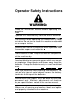
CONTROL HANDLE I SOLUTION “ON” LIGHT SOLUTION CONTROL LEVER MAIN SWITCH BATTERY CONDITION LIGHTS LIGHTED VACUUM SWITCH BRUSH “ON” LIGHT TRAVERSE CONTROL HANDLE Controls flow of cleaning solution to floor. Light “ON” indicates solution valve is open. Indicates charge condition of batteries 4 green lights - full charge - approximately 4 112 hours run time. 1 green light - approximately 112 hour run time left. Switches on main drive motor and brush. Light “ON” indicates brush is turning.
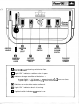
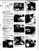
, MACHINE PREPARATION BAITERIES 1. Install batteries and connect battery cables as shown. RE NOTE This pedal can also be used to Increase brush pressure to the floor. This can be done by pulling up on the pedal and locking it in one of the positions on the brush adjustment bracket. 3. Attach brush or drive pad to drive plate. MfARN/NG: Provide proper ventilation and leave cover open when charging batteries. BRUSH/DRIVE PAD ASSEMBLY 1. Remove brush cover. 2.
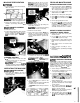
- 2. Check motor brushes when worn to 318" length replace both brushes. DRIVE CHAIN BATTERY MAINTENANCE 1. Remove left side skirt and side panel. 1. Keep tops of batteries clean and dry. Use a damp cloth with a weak SOlutlOn of baking soda or ammonia and water. Use a clean dry cloth to wipe battery tops dry after cleaning. 2. To remove chain, remove retaining clip and pull out master link. 2. Remove pulley to allow removal of left hand lift arm. 3. Remove right hand pivot bolt, bushing and lift arm.
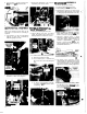
4. Lift out motor - check motor brushes. When worn to 318" replace brushes. 3. Remove axle hub clamps. Lift off assembly and lay on bench to service. SQUEEQEEASSEMBLY To remove squeegee assembly.. . 1. Depress pedal to raise squeegee. 2. Pull retaining pin from locator stud. 3. Push down on squeegee to remove from drag arm and slide squeegee to the right to disengage right hand stud from arm.
2. After installing new belt check for clearance between traverse pulley and brush drive belt. The pulley should not be in contact with the belt when the traverse handle is in the neutral position. BRUSH DRIVE BELT To adjust clearance: 1. Remove traverse drive belt by rolling belt A. Remove left side panel. off pulley. B. Loosen lock nuts on link rod. Adjust 2. Loosen belt tension adjusting screw and bracket on link rod so pulley does not remove brush drive belt. After readjustcontact belt.
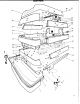
' VAC, BATTERY, TANK 7 VAC, BATTERY, TANK REV PARTNO.
17 AI 16 9
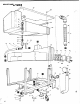
' MAINFRAME WITANKS 34 37 38 35 36 I 41' "1 13 14, io 46 / 39
SQUEEGEE w/ARM 59 69 --1 21 I 11 . . ~ __ . . . ..-. . , . ,... - . ..
CONTROLS (MECHANICAL) ~ONTROLS(MECHANICAL) KEY 1 2 3 4 5 6 7 8 9 10 11 12 13 14 15 16 17 18 19 20 21 22 23 24 25 26 27 28 29 30 31 32 33 34 35 36 37 . 38 PART NO. DESCRIPTION 05029 70015 87090 14492 70270 05030 70260 87087 14493 57105 05033 14491 70265 73268 57117 67114 87096 27277 66116 66121 70273 87003 90002 57112 57104 67122 14509 62190 62211 70085 57047 61102 70054 38131 36084 48030 38133 70057 Arm. Drive Linkage Adj Scr. 1/4-20 x 314 HHMS Washer, 1/4 ID x 3/4 OD Bushing, .25 ID x .37 OD x .
48 49 50
‘IAL - 39 14 2 1
PT.20 LABELS PART NO.
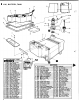
-;:"BRUSHDRIVE I . 74 - Reduction Gearbox Assembly 1 BRUSH DRIVE KEY PART NO. DESCRIPTION 53 671 12 54 57022 55 66105 56 67104 57 70260 58 87056 59 20068 60 73317 61 73318 62 73319 63A 02095 638 02096 63C 02097 630 02098 64 59020 65 57133 66 73320 67 67144 68 73313 69 36090 70 67143 71 62202 72 70304 73 51076 74 36076 16 Rod, Turnbuckle Sliding Nut, 3/8-16 Lock Pin, Turnbuckle Ring, 518 Ext Snap H-D Scr, M 6 x 16 Washer, M6 Clamp, PT-20 Brush Shim, 12mm Dia. Shim, 15mm Dia.
I ' " Product Modification Pi-20 BATTERY SC RUBB ER Beginning with Serial #I700 the following changes were made to the brush drive as shown on Page 16 in the .service manual. Retain t h i s notice in your manual for reference when ordering replacement parts. 1. Key #44 - Changed to rod with lock nuts, replacing the snap rings. 2. Keys #1-2-3-4-6-35-72-73-74-75-76-77 - Changed drive plate, brush drive lock, and new gear u n i t assembly. 43 42 41 40 39 37 38 I b18 (Rev.
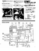
I 7 J. PROBLEM PROBABLE CAUSE CORRECTIVE ACTION No power. Circuit breaker tripped. Battery cables corroded at battery terminals. Faulty main switch. Reset brush motor circuit breaker (50 amp). 1. Clean battery cable clamps and battery terminals. 2. Check voltage at points A and B. Voltage should be 22/26 VDC. 1. Check voltage at points A and C. Voltage should be 22/26 VDC. 2. Turn main switch on and check voltage at points A and D. Voltage should be 22/26 VDC.