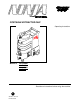
PORTABLE EXTRACTOR-240V Operating Instructions MODELS: 621-222MO 10070460 621-225MO 10070470 Read these instructions before using the machine V 86038610 04/21/08 PRV NO.
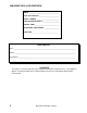
MACHINE DATA LOG/OVERVIEW MODEL _______________________________________ DATE OF PURCHASE __________________________ SERIAL NUMBER ______________________________ SALES REPRESENTATIVE # _____________________ DEALER NAME ________________________________ OPERATIONS GUIDE NUMBER ___________________ PUBLISHED __________________________________________ YOUR DEALER Name: __________________________________________________________________________________________________ Address: __________________________________
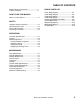
TABLE OF CONTENTS Machine Data Log/Overview.........................2 Table of Contents..........................................3 HOW TO USE THIS MANUAL How to use this Manual.................................1-1 SAFETY Important Safety Instructions ........................2-1 Hazard Intensity Level. .................................2-2 Safety Label Location. ..................................2-3 Grounding Instructions..................................2-4 GROUP PARTS LIST Frame Group (200 psi) ..........
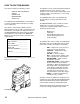
HOW TO USE THIS MANUAL This manual contains the following sections: - - HOW TO USE THIS MANUAL SAFETY OPERATIONS MAINTENANCE PARTS LIST The HOW TO USE THIS MANUAL section will tell you how to find important information for ordering correct repair parts. Parts may be ordered from authorized dealers. When placing an order for parts, the machine model and machine serial number are important. Refer to the MACHINE DATA box which is filled out during the installation of your machine.
SAFETY INSTRUCTIONS IMPORTANT SAFETY INSTRUCTIONS When using an electrical appliance, basic precaution must always be followed, including the following: READ ALL INSTRUCTIONS BEFORE USING THIS MACHINE. This machine is for commercial use. ! WARNING: To reduce the risk of fire, electric shock, or injury: Connect to a properly grounded outlet. See Grounding Instructions. Do not leave the machine unattended. Unplug machine from outlet when not in use and before maintenance or service. Use only indoors.
HAZARD INTENSITY LEVEL The following symbols are used throughout this guide as indicated in their descriptions: HAZARD INTENSITY LEVEL There are three levels of hazard intensity identified by signal words -WARNING and CAUTION and FOR SAFETY. The level of hazard intensity is determined by the following definitions: ! WARNING WARNING - Hazards or unsafe practices which COULD result in severe personal injury or death.
SAFETY LABEL LOCATION NOTE: These drawings indicate the location of safety labels on the machine. If at any time the labels become illegible, promptly replace them. LABEL WARNING 86242230 PRV NO. 500009 LABEL CIRCUIT INTERRUPTER 86200570 PRV NO.
GROUNDING INSTRUCTIONS THIS PRODUCT IS FOR COMMERCIAL USE ONLY. ELECTRICAL: The amp, hertz, and voltage are listed on the data label found on each machine. Using voltages above or below those indicated on the data label will cause serious damage to the motors. EXTENSION CORDS: If an extension cord is used, the wire size must be at least one size larger than the power cord on the machine, and must be limited to 50 feet (15.5m) in length. GROUNDING INSTRUCTIONS: This appliance must be grounded.
THIS PAGE LEFT BLANK INTENTIONALLY NINJA INTL 86038610 03/29/07 2-5
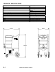
TECHNICAL SPECIFICATIONS ITEM ELECTRICAL Vacuum Motor Solution Pump MEASURE 230 Volt, 50 hz Dual 2 stage 200 psi 500 psi 10 gal (38 L) 8 gal (240 kg) 110 lbs (240 kg) 200 lbs (440 kg) 36 inches (91.44 cm) 29 inches (73.66 cm) 19.5 inches (49.53 cm) 22 feet (6.
CONTROLS BY CENTURY 400 1 2 3 1. Pump Switch 2. Vacuum #1 Switch 3.
MACHINE OPERATION EMPTYING AND CLEANING PRE-RUN INSPECTION 1. Check all fittings and connectors for proper assembly. 2. Check all hoses for leaks. Repair or replace any damaged hoses. 3. Check power cord(s) for any damage. If damaged, replace. Always use defoamer if foaming occurs. Foam will suspend large particles that may damage vacuum(s) as well as allow liquid into the vacuum motor(s) without activating the float shutoff. 1. Before proceeding, make certain that the nozzle is functioning properly.
MAINTENANCE DAILY MAINTENANCE Unplug power cord(s) before servicing or making any repairs. 1. Flush the entire system, including floor tool, hand tool, etc., with 1 to 3 gallons of clean, hot water. 2. Vacuum out the solution tank. 2. Check hoses for wear, blockages, or damage. Frayed or cracked hoses should be repaired or replaced to eliminate vacuum or solution pressure. 3. Check all handles, switches, knobs, electrical cables and connections on your machine for damage.
MAINTENANCE Only qualified maintenance personnel are to perform the Vacuum Motor Carbon Brushes Replacement (Ametek) End Cap following repairs. VACUUM MOTOR REPLACEMENT 1. Turn off all switches and unplug machine. Carbon Brushes WARNING: The green ground wire must be attached for safe operation. See wiring diagram. 2. Remove recovery tank. 3. Locate the vacuum motor wires and disconnect at the connector. 4. Remove the vacuum motor. 5. Reverse process to install vacuum motor.
MAINTENANCE PUMP REPLACEMENT KITS 200 PSI CAM & BEARING KIT 862011470 PRV NO. 250-79G VALVE & O-RINGS KIT 86201160 PRV NO. 250-79F PLUNGER & SEALS KIT 86201150 PRV NO. 250-79E PUMP REPLACEMENT KITS 500 PSI CAM & BEARING KIT 86201040 PRV NO. 250-73C VALVE & O-RINGS KIT (BOTH SIDES) 86201030 PRV NO. 250-73B PLUNGER & SEALS KIT 86201080 PRV NO.
MAINTENANCE PRESSURE REGULATOR For best results with the pressure regulator, we recommend that you clean and lubricate the piston and u-cup with Superlube lubricant monthly or when pressure drop seems excessive. 1. Turn unit off before lubricating. 2. Remove cap, spring and spring retainer plate. 3. With fingertips remove piston and u-cup. 4. Wipe piston and u-cup clean of any film or scale. 5. Lubricate the piston and u-cup with Superlube. 6. Reassemble regulator. 7.
TROUBLESHOOTING PROBLEM Loss of Power Electrical shock CAUSE SOLUTION Dead electrical circuit Faulty power cord Equipment not grounding Receptacle not grounded Check building circuit breaker or fuse box.
FRAME GROUP (200 PSI) 2 3 1 4 26 5 27 6 8 7 7 25 24 23 22 4 10 11 6 21 9 19 28 12 MP PU O FF O FF ON O FF ON 13 ON CE 14 5-1 URY NT 40 C 0 IN 4 15 16 17 20 11 NINJA INTL 86038610 03/29/07 18
FRAME GROUP (200 PSI) REF PART NO. PRV NO.
FRAME GROUP (500 PSI) 5 4 3 2 1 7 8 33 6 12B 32 29 9 4 10 11 12A 12B 30 28 25 13 27 16 24 34 16 4 17 18 14 15 23 19 12A 16 5-3 31 22 21 20 NINJA INTL 86038610 03/29/07
FRAME GROUP (500 PSI) REF PART NO. PRV NO.
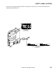
PUMP GROUP (200 PSI) 1 2 1 1 9 3 6 4 14 15 5 9 7 2 8 1 16 10 11 12 17 18 19 5-5 NINJA INTL 86038610 03/29/07 13 1 3
PUMP GROUP (200 PSI) REF PART NO. PRV NO. QTY 1 2 3 4 5 6 7 8 9 10 11 12 13 14 15 16 17 18 19 86233150 86280750 86068520 86199230 86005590 86197670 86272730 86247710 86197370 86005810 86010630 86020350 86200130 86200940 86282310 86197550 86258970 86197670 86197760 20042 151-38A 40028 250-33 56014 56023 66017 56022 31017 57245 87013 70019 151-37C 65227 39699 40014 84193 56023 78308 5 2 2 1 1 1 1 1 2 2 4 2 1 1 1 1 1 1 1 DESCRIPTION SERIAL NO.
PUMP GROUP (500 PSI) 1 1 2 16/17 21 1 15 3 4 5 8 1 7 6 7 1 9 6 6 10AB 1 14 17 5-7 8 11 16 18 13 13 27 12 19 NINJA INTL 86038610 04/21/08 6
PUMP GROUP (500 PSI) REF PART NO. PRV NO.
RECOVERY & SOLUTION TANK GROUP 1 4 3 36 35 33 32 7 34 5 10 2 8 6 9 31 10 11 30 29 19 20 12 21 22 23 13 14 5-9 23 24 36 18 15 28 27 22 16 25 17 16 NINJA INTL 86038610 03/29/07 26
RECOVERY & SOLUTION TANK GROUP REF PART NO. PRV NO.
VACUUM MOTOR GROUP 22 21 20 14 6 1 5 2 7 3 15 4 13 16 5 12 17 11 19 10 7 6 8 18 9 5-11 NINJA INTL 86038610 03/29/07 4
VACUUM MOTOR GROUP REF PART NO. PRV NO.
WIRING GROUP (200 PSI) 5-13 NINJA INTL 86038610 03/29/07
WIRING GROUP (500 PSI) NINJA INTL 86038610 03/29/07 5-14