
Operating instructions

2.
3
U
n
2.
4
If t
h
dr
a
th
a
ca
n
9/1
th
a
wi
t
str
a
TP-4976
4
January
2
3
UNPACKI
N
n
pack the INF
1. Carefully
2. Lift the u
n
symbol.
3. Inspect f
o
4. Be sure
t
4
ATTACHI
N
h
e INFLEXI
O
a
in holes (on
e
a
t water drain
n
not be sub
m
1
6” bolt holes
a
t the saddle
t
hstand oper
a
a
in relief hol
e
4
01-B
2
014
N
G
LEXION as f
o
open and re
m
n
it from the s
o
r any shippi
n
t
hat all comp
o
N
G TO VEHI
C
O
N is mounte
d
e
per corner)
s out of the
w
m
erged.
will be need
and base pl
a
a
ting loading.
e
s in the side
o
llows:
m
ove all part
s
h
ipping cont
a
n
g damage.
I
o
nents are in
c
C
LE
d
in a well o
n
at least half
w
ell. While t
h
e
d to mount
m
a
te are in the
Torque all
h
of the base f
o
INFL
E
S
e
s
from shippi
n
a
iner by the b
a
I
f damage ha
c
luded and th
n
a vehicle, b
e
inch in diam
e
h
e unit has b
e
m
ast (Figure
same plane.
h
ardware as
o
r cable entr
y
F
E
XION 4.5 M
o
e
e section 1.
4
n
g container.
a
se tube at t
h
s occurred, n
at the requir
e
e
certain that
e
ter is recom
m
e
en designe
d
2-1) to the v
e
The areas
t
appropriate
f
y
.
F
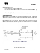
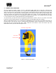
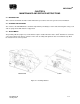
igure 2-1
o
unting Hole
4
for other ho
h
e center of
g
n
otify carrier.
e
d tools are r
e
adequate dr
a
m
ended to b
e
d
to withstan
d
e
hicle. It is i
m
t
o which the
u
f
or its materi
a
Pattern Sho
w
le patterns.
g
ravity of the
m
e
adily availa
b
a
inage is pro
e
drilled in th
e
d
adverse en
v
m
portant tha
t
u
nit is mount
a
l and size.
T
w
n
INFL
E
m
ast shown
b
b
le.
vided.
A
mi
n
e
well aroun
d
v
ironmental
c
t
the surface
ed must be
r
T
here are (3
)
E
XION
TM
2-5
b
y the
n
imum of (4)
d
the unit so
c
onditions, it
be flat such
r
einforced to
)
unplugged