M INFLE EXIONTM 2.3, 4.5 5, 6.0 & 7.5 INS STALLAT TION, OPERATION & M MAINTEN NANCE M MANUAL The Will-Bu urt Company 169 S.. Main Street Orrville e, OH 44667 www.willburt.
INFLEXIONTM Inflexion™ Warranty Will-Burt warrants its Inflexion™ masts to be free from defects in material and workmanship for a period of two (2) years, with such time period running from the date of shipment by Will-Burt.
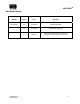
INFLEXIONTM Document History Manual Version Date Remarks TP-4976401 00 11/12/2013 INITIAL RELEASE A 12/3/2013 Updated warranty page. B 01/06/14 Clarify power requirements (section 1.6), emergency stow procedure (section 3.
INFLEXIONTM TABLE OF CONTENTS SAFETY SUMMARY..................................................................................................................................... vii 1. INTRODUCTION 1-1 1.1 Safety Precautions ................................................................................................................................ 1-1 1.2 Document Introduction ..........................................................................................................................
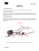
INFLEXIONTM LIST OF ILLUSTRATIONS Figure 1-1 Figure 1-2 Figure 2-1 Figure 3-1 Figure 3-2 Figure 4-1 Figure 4-2 INFLEXION Mast Major Components (INFLEXION 4.5, model 720378040 shown) .............. 1-1 INFLEXION 4.5 Model Number 722069001 Dimensions ........................................................ 1-3 INFLEXION 4.5 Mounting Hole Pattern ................................................................................... 2-5 Hand-held Controller .......................................................
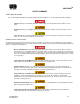
INFLEXIONTM SAFETY SUMMARY SIGNAL WORD DEFINITION Per the ANSI Z535.4 standard, the following signal words and definitions are used to indicate hazardous situations: DANGER indicates an imminently hazardous situation that, if not avoided, will result in death or serious injury. WARNING indicates a potentially hazardous situation that, if not avoided, could result in death or serious injury. CAUTION indicates a potentially hazardous situation that, if not avoided, may result in minor or moderate injury.
INFLEXIONTM SPECIFIC SAFETY PRECAUTIONS The following are safety precautions that are related to specific procedures and therefore appear elsewhere in this publication for emphasis. These are recommended precautions that personnel must understand and apply during specific phases of installation, operation and maintenance. Safety Instruction-Operation! For outdoor use only. Do not use in areas that have been classified as hazardous as defined in Article 500 of the National Electric Code.
INFLEXIONTM When relamping an installed fixture, make sure all power to fixture is off and that the fixture is cool Safety Instruction – Operation! At all times prior to mast operation, insure that: 1.) 2.) 3.) 4.) 5.) 6.
INFLEXIONTM CHAPTER 1 INTRODUCTION 1.1 SAFETY PRECAUTIONS Refer to the Safety Summary for precautions to be observed while operating or servicing this equipment. 1.2 DOCUMENT INTRODUCTION This document covers installation, operation, maintenance, and troubleshooting for the INFLEXION masts. The manual should be reviewed in its entirety. Contact the Will-Burt factory with any questions before performing any procedures outlined in this manual. The INFLEXIONTM 1.5, 2.3, 4.5, 6.0, and 7.
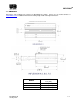
INFLEXIONTM 1.4 DIMENSIONS Dimensions and mounting hole locations for INFLEXION are shown. Please refer to product literature or www.willburt.com for additional information including length, width and height information. MODEL TP-4976401-B January 2014 DIM "X" inch [mm] 4.5 METER 66 5/8 [1692.3] 6.0 METER 79 7/8 [2028.8] 7.5 METER 94 3/8 [2397.
INFLEXIONTM Figure 1-2 INFLEXION 4.5 Model Number 722069001 Dimensions 1.5 MAST LOAD It is important that the mast be securely mounted to a sturdy platform, which will not overturn during operational loading of the mast. Following is the loading information for the mast, which can be expected during operation: 75 lb at saddle of mast (Inflexion 1.5 and 2.3) or 120 lb saddle of mast (Inflexion 3.0, 4.5, 6.0, and 7.
INFLEXIONTM CHAPTER 2 INSTALLATION Safety Instruction -Trained Personnel Only! Only trained and qualified personnel should perform installation, adjustments, and servicing. Only a properly trained and qualified certified electrician should perform electric installations and service. Safety Instruction -Trained Personnel Only! Only trained and qualified personnel should perform installation, adjustments, and servicing.
INFLE EXIONTM 2.3 3 UNPACKIN NG Un npack the INFLEXION as fo ollows: 1. Carefully open and rem move all parts s from shippin ng container. 2. Lift the un nit from the shipping conta ainer by the ba ase tube at th he center of g gravity of the m mast shown b by the symbol. 3. Inspect fo or any shippin ng damage. If I damage has occurred, n notify carrier. 4. Be sure that t all compo onents are inc cluded and that the require ed tools are re eadily availab ble. 2.
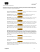
INFLE EXIONTM 2.5 5 CONNECTING DC POW WER TO THE BASE 1. From the customer supplied 12 VDC power supply, run th he red and black 12V DC power wires tthrough one of the east AWG 12 e strain reliefs s in the side of o the base. Ensure E the ca ables are at le 2 and no long ger than 50ft from the t power sup pply to the ba ase board. 2. Locatte terminal blo ock TB3. Term minal Block TB3 3 3. Connect the positiv ve, red, 12 VD DC cable to 7 PWR and co onnect the ne egative, black, cable to 8 C COM.
INFLEXIONTM 4. Upon receipt of the INFLEXION, the hand-held controller should already be wired to the green base board connector. 2.6 PRE-OPERATIONAL CHECK Before beginning installation, make certain that the area is free of overhead power lines and other unwanted sources of electricity. Follow OSHA safety regulations when working near energized power lines. Be sure to allow sufficient clearance on all sides of mast to allow for side sway. This mast is for outdoor use only.
INFLEXIONTM CHAPTER 3 OPERATING INSTRUCTIONS All operators must read the Operation section of this manual and be properly trained. Keep personnel clear of mast while during operation. For outdoor use only. Do not use in areas that have been classified as hazardous as defined in Article 500 of the National Electric Code. Do not use in the presence of flammable gases or liquids such as paint, gasoline or solvents. Do not use in areas of limited ventilation or where high ambient temperatures are present.
INFLEXIONTM 3.1 GENERAL MAST OPERATION The mast hand-held controller (Figure 3-1).has a momentary toggle switch and a cord that is wired into the baseboard. When the “Mast Up” button is pressed and held, the INFLEXION operates the DC powered actuator and drives the mast from the stowed position to the 90o position. Releasing the “Mast Up’ switch at any time stops mast motion. Note there is no Auto-up feature to automatically raise the mast to 90o.
INFLEXIONTM 3.2 EMERGENCY STOW (LOSS OF POWER): Make sure all power has been disconnected from the INFLEXION prior to manually lowering mast. In the event of power loss, the INFLEXION mast will vent and lower automatically but the mast will not return to its fully stowed horizontal position. If possible, this must be accomplished manually and must be done with extreme caution.
INFLEXIONTM CHAPTER 4 MAINTENANCE AND SERVICE INSTRUCTIONS 4.1 INTRODUCTION This section of the manual describes routine maintenance procedures and covers general service information. 4.2 CLEANING THE INFLEXION The exterior of the INFLEXION base should be wiped down periodically to remove dirt and road grime using a soft cloth or sponge and a mild solution of soapy water. 4.3 ADJUSTMENTS The proximity switches (Figure 4-1) are intended to stop the actuator when the mast is at 90o and when it is stowed.
INFLEXIONTM Adjusting the 90o Proximity Switch Before delivery of a new INFLEXION, all switches are properly set and tested and normally no switch adjustment is necessary. However, if the 90o switch needs adjusted, like after the actuator was replaced, follow these steps to adjust the 90o switch: 1. Make certain that the INFLEXION base is level. 2. Remove the base side cover. 3. Loosen the upper jam nut to lower the switch approximately 1/8”. 4.
INFLEXIONTM 4.4 TROUBLESHOOTING Refer to Table 4-1 troubleshoot INFLEXION issues. WARNING: Only trained and qualified personnel should install, adjust, service and use INFLEXION. WARNING: Before troubleshooting, read the operating instructions and the safety summary. Always obey the warnings in the operating instructions.
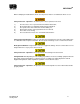
INFLEXIONTM LED TP-4976401-B January 2014 Definition Power 12V is at the base board Mast active Mast is out of the saddle Lights active Mast is at 90 Tilt Up or Down Not Used Pan Right or Left Not Used Not 90 Deg Mast is not at 90 RCP active Not Used Not up Always lit when the mast is at 90 RCP run Not Used Down Not Used Full lights Not Used Up input Mast up key pressed Down input Mast down key pressed Half lights Not Used o o o 4-7
INFLEXIONTM Figure 4-2 Status LEDs on Base Board PROBLEM Actuator is not functioning at all. Actuator is not functioning properly in the UP direction. Actuator is not functioning properly in the DOWN direction CAUSE EVIDENCE Blown fuse FU1 or FU2 on circuit board. No status LEDs are lit on the control board. MAST UP/DOWN switch in remote Operator Station is defective. Neither the “UP INPUT” nor the “DOWN INPUT” status LEDs light when the corresponding switch is activated. Actuator is defective.