CARPET EXTRACTOR Operating Instructions (ENG) MODEL: D250 (115V) Beginning with Serial No.
TABLE OF CONTENTS MODEL DATE OF PURCHASE SERIAL NUMBER SALES REPRESENTATIVE # DEALER NAME Data Log/Table of Contents ...............1 Technical Specifications……………..10 Safety Instructions .............................2 Wiring Diagram ..................................11 Grounding Instructions.......................3 Parts Lists ..........................................13-16 Operations..........................................4 Spare Parts ........................................
SAFETY INSTRUCTIONS IMPORTANT SAFETY INSTRUCTIONS When using an electrical appliance, basic precaution must always be followed, including the following: READ ALL INSTRUCTIONS BEFORE USING THIS MACHINE. This machine is for commercial use. ! WARNING: To reduce the risk of fire, electric shock, or injury: Connect to a properly grounded outlet. See Grounding Instructions. Do not leave the machine unattended. Unplug machine from outlet when not in use and before maintenance or service. Use only indoors.
GROUNDING INSTRUCTIONS THIS PRODUCT IS FOR COMMERCIAL USE ONLY. ELECTRICAL: The amp, hertz, and voltage are listed data label found on each machine. voltages above or below those indicated data label will cause serious damage motors. on the Using on the to the GROUNDING INSTRUCTIONS: This appliance must be grounded. If it should malfunction or break down, grounding provides a path of least resistance for electric current to reduce the risk of electric shock.
OPERATIONS CARPET INSPECTION: PROTECT THIS MACHINE FROM FREEZING. Determine precisely what areas you are going to clean. Note problem areas in the carpet or tack strip. Look for loose carpet, heavily damaged areas, discolored stains, or grease spots that will require prespotting. Note the carpet type. Check the availability of hot water, drains, and suitable electrical outlets. If the carpet is loose or worn, have it repaired before attempting to clean it.
OPERATION 3. HEATER OPERATION The disconnect fittings on the heater will become extremely hot during operation. Allow sufficient time to cool, or run solution through the machine with the heater turned off before disconnecting the or performing any maintenance on the heater. Before disconnecting the heater, open wand valve to relieve the system of all pressure by depressing the valve trigger. DO NOT spray water directly on to the heater. To clean, unplug the unit and wipe with a damp cloth.
MAINTENANCE DAILY MAINTENANCE: 3.) (At the end of each working day) : 1.) Flush the entire system, including floor tool, hand tool, etc., with 1 to 3 gallons of clean, hot water. 2.) Vacuum out the solution tank . 3.) Rinse tank with fresh water. Periodically inspect the recovery tank and decontaminate if necessary, using a Hospital Grade Virucide or a 1-10 bleach to water solution. Waste water should be disposed of properly. 4.) Remove lint build-up from the float shut-off screen in the recovery tank .
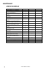
MAINTENANCE SERVICE SCHEDULE MAINTENANCE Check machine for cord damage Check recovery dome and gasket for damage and cleanliness Check hoses for wear, blockages, or damage Check handles, switches, and knobs for damage Check vac motor intake filter and clean Run one gallon of water through system Clean out recovery tank and check float valve to make sure it moves freely Clean out solution tank and remove and clean vacuum intake screen Clean outside of all tanks and check for damage Run vac motor for at least
MAINTENANCE ! WARNING: ONLY QUALIFIED MAINTENANCE PERSONNEL ARE TO PERFORM THE FOLLOWING REPAIRS. Vac Motor Carbon Brushes Replacement End Cap VACUUM MOTOR REPLACEMENT 1. Turn off all switches and unplug machine. 2. Remove recovery tank. Carbon Brushes 3. Locate the vacuum motor wires and disconnect at the connector. 4. Remove the vacuum motor. 5. Reverse process to install vacuum motor. WARNING: The green ground wire must be attached for safe operation. See wiring diagram.
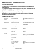
MAINTENANCE & TROUBLESHOOTING D-250 PUMP MAINTENANCE Per manufacturer’s recommendations the following maintenance should be performed utilizing noted kits: 1.) 500 hours-Kit 55250751 replaces the V-packing, wave washer, packing spreader and plunger guide. 2.) 500 hours-Kit 55250753 replaces the CAM bearing and insert. 3.) 1000 hours-kit 55250752 valve assembly and o-rings. NOTE: Maintenance and repairs must be done by qualified personnel. Using nonWindsor parts to repair this machine will void the warranty.
TROUBLESHOOTING CONT. Solution hose fitting hard to connect Corrosion on fittings Clean with steel wool. Soak in acetic acid (white vinegar). Lubricate lightly with silicone base lubricant. Carpet not getting clean. Severe soil conditions Make several passes at right angles to other. Use a prespray. Carpet too wet Over saturation Adjust solution pressure to lower setting. Make several passes without spray. Carpet browning Leaving carpet too wet Check for loss of vac pressure.
115V WIRING DIAGRAM 11 D-250 98828 06/07/03
THIS PAGE LEFT BLANK INTENTIONALLY D-250 98828 04/08/03 12
RECOVERY TANK ASSEMBLY 1 2 6 3 5 29 4 28 34 13 7 27 26 13 8 9 25 35 10 11 12 14 33 15 16 13 17 36 24 18 19 30 22 21 20 31 32 13 D-250 98828 06/07/03 23
RECOVERY TANK ASSEMBLY REF PART NO. QTY 1 2 3 4 5 6 7 8 9 10 11 12 13 14 15 16 17 18 19 20 21 22 23 24 25 26 27 28 29 30 31 32 33 34 35 36 05151 500009 260-64A 70546 090-12A 78475 320-05 15-808123 11-800444 390-26 35168 360-24 87013 35166 065-92 85047 70813 87016 70335 20063 39337 27508 20046 880292 75334 70015 065-25 70020 40001R 39574 150-44A 47356 150-65 35255 35256 57105 1 1 1 6 1 1 2 1 1 3 1 1 7 1 3 1 1 3 1 1 1 1 1 1 1 2 1 2 1 1 1 1 1 1 1 3 SERIAL NO.
SOLUTION TANK ASSEMBLY 6 5 31 4 7 8 3 2 63 9 67 68 12A 1 10 41 69 13 11 31 14 66 70 65 30 29 15 64 28 16 18 32 27 26A 17 74 63 33 25 24 19 23 34 62 71 22 60 61 38 21 35 37 20 8 36 38 59 8 39 38 73 40 41 58 72 54 53 43 52 57 42 46 31 56 51 76 55 50 44 8 49 48 45 46 47 15 D-250 98828 06/07/03 38
SOLUTION TANK ASSEMBLY REF PART NO.
SOLUTION TANK ASSEMBLY CONT'. REF PART NO. QTY 54 55 56 57 58 59 60 61 62 63 64 65 66 67 68 69 70 71 72 73 74 75 76 70232 57196 040-06 010-01 065-28 040-03 290-08 75349 500378 280-02 390-24 140-12 27912 260-71 56012 250-35 151-50B 250-15 41393 70127 48100 57037 70393 2 2 1 1 2 1 1 1 2 2 2 1 1 2 1 1 1 1 1 4 1 1 2 SERIAL NO.
WINDSOR INDUSTRIES New Machine Warranty Limited Warranty Windsor Industries, Inc. warrants new machines against defects in material and workmanship under normal use and service to the original purchaser. Any statutory implied warranties, including any warranty of merchantability or fitness for a particular purpose, are expressly limited to the duration of this written warranty.
WINDSOR INDUSTRIES New Machine Warranty 90 Day Warranty Extension Available Upon receipt of the Machine Registration Card, Windsor will extend by 90 days, from the date of purchase, all items included under the one-year provision. This applies only to one-year items and does not include 90-day wear items. This Warranty Shall Not Apply To: 1.