Operating instructions (ENG) MODELS: CS20 10061250 CSC20 10061330 CSX20 10061370 CSXC20 10061380 CS22SP 10061300 CSC22SP 10061340 From Serial Number (1*) See Serial number page or call manufacturer. Read these instructions before using the machine.
Machine Data Label Overview The Chariot Scrubber is a battery powered, stand-on, hard floor scrubber intended for commercial use. The appliance applies a cleaning solution onto a hard floor, scrubs the floor with brush or pad, and then vacuums the soiled water back into the recovery tank. Warranty Registration Thank you for purchasing a Windsor product. Warranty registration is quick and easy. Your registration will allow us to serve you better over the lifetime of the product.
Table of Contents Machine Data Label . . . . . . . . . . . . . . . . . . . . . . . . . . 2 Table of Contents . . . . . . . . . . . . . . . . . . . . . . . . . . . 3 How To Use This Manual . . . . . . . . . . . . . . . . . . . . . 4 Safety IMPORTANT SAFETY INSTRUCTIONS . . . . . . . . . 5 HAZARD INTENSITY LEVEL . . . . . . . . . . . . . . . . . . 7 SAFETY LABEL LOCATIONS . . . . . . . . . . . . . . . . . 9 Operations Technical Specifications . . . . . . . . . . . . . . . . . . . . .
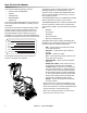
How To Use This Manual The SAFETY section contains important information regarding hazardous or unsafe practices of the machine. Levels of hazards are identified that could result in product damage, personal injury, or severe injury resulting in death. This manual contains the following sections: • • • • • HOW TO USE THIS MANUAL SAFETY OPERATIONS MAINTENANCE PARTS LIST The OPERATIONS section is to familiarize the operator with the operation and function of the machine.
Safety IMPORTANT SAFETY INSTRUCTIONS When using this machine, basic precaution must always be followed, including the following: READ ALL INSTRUCTIONS BEFORE USING THIS MACHINE. To reduce the risk of fire, electric shock, or injury: Use only indoors. Do not use outdoors or expose to rain. Use only as described in this manual. Use only manufacturer's recommended components and attachments.
Safety MESURES DE SÉCURITÉ IMPORTANTES Lors de l'utilisation d'un appareil à batteries, il est nécessaire de respecter systématiquement des mesures de sécurité de base, comme suit : PRENEZ NOTE DE TOUTES CES MESURES AVANT D'UTILISER CETTE MACHINE. Pour réduire les risques d'incendie, de chocs électriques, ou de blessures : N'utiliser cette machine qu'en intérieur. Ne jamais l'utiliser à l'extérieur ou dans la pluie. N'utiliser cette machine que comme décrit dans le présent manuel.
Safety The following symbols are used throughout this guide as indicated in their descriptions: HAZARD INTENSITY LEVEL There are three levels of hazard intensity identified by signal words -WARNING and CAUTION and FOR SAFETY. The level of hazard intensity is determined by the following definitions: WARNING - Hazards or unsafe practices which COULD result in severe personal injury or death. CAUTION - Hazards or unsafe practices which could result in minor personal injury or product or property damage.
Safety Les symboles ci-dessous sont utilisés à travers ce manuel comme illustré dans leurs descriptions : DEGRÉS DE RISQUES EN CAS DE DANGER Il existe trois degrés de risques identifiés par les termes signalétiques -AVERTISSEMENT et ATTENTION et POUR VOTRE SÉCURITÉ. Le degré de risque est défini de la manière suivante: AVERTISSEMENT - Dangers ou méthodes dangereuses qui POURRAIENT provoquer de graves blessures ou entraîner la mort.
Safety SAFETY LABEL LOCATIONS These drawings indicate the location of safety labels on the machine. If at any time the labels become illegible, promptly replace them. EMPLACEMENT DE L'ÉTIQUETTE DE SÉCURITÉ REMARQUE : Ces dessins indiquent l'emplacement des étiquettes de sécurité sur la machine. Si, à tout moment, les étiquettes deviennent illisibles, contactez votre représentant autorisé pour un remplacement rapide. 86244300 PRV NO. 500955 WARNING LABEL CAUTION 86244310 PRV NO.
Operations Technical Specifications ITEM Nominal Power-Disk Nominal Power-Cylindrical Rated Voltage Rated Amperage -Disk Rated Amperage -Cylindrical Batteries Battery Compartment Dimensions Scrub Brush Motor - Disk Machine Scrub Brush Motor - Cylindrical Machine Vacuum Motor Maximum flow rate of vacuum motor Maximum suction of vacuum motor Propelling Motor Mass (GVW) Weight empty without batteries - Disk Weight empty without batteries - Cylindrical Solution Control Solution capacity Recovery capacity Scrub
Operations ITEM Height Length Width without squeegee - Disk Width without squeegee - Cylindrical Width of squeegee - Disk Width of squeegee - Cylindrical Width of scrub path - Disk Width of scrub path - Cylindrical MEASURE 51.8 in (1316mm) 44.0 in (1118mm) 23.4 in (594mm) 25.4 in (645mm) 27.2 in (691mm) 29.
Operations How This Machine Works The Chariot® is a battery powered, self-propelled, hard floor scrubber intended for commercial use. The appliance applies a cleaning solution onto a hard floor, scrubs the floor with a brush, and then vacuums the soiled water back into the recovery tank. The machine's primary systems are the solution system, scrub system, recovery system, and operator control system. The function of the solution system is to store cleaning solution and deliver it to the scrub system.
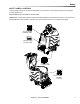
Operations 7 3 1 2 10 5 4 6 9 11 12 8 10 Deluxe Disk & Cylindrical 9 Cylindrical 12 Components 1. Drive Control 2. Scrub Controls 3. Control Console 4. Pedal Platform 5. Solution Tank 6. Recovery Tank 7. Recovery Sight Dome 8. Recovery Drain Hose 9. Scrub Deck Skirt 10. Solution Cover 11. Solution Drain Hose/Solution Level Indicator 12.
Operations Drive Controls 1 8 9 5 2 3 7 6 4 10 14 86359770 - CS20 SCRUBBER
Operations 2. EMERGENCY STOP/BRAKE SWITCH 1. Key Switch 2. Emergency Stop/Brake Switch 3. Directional Control / Drive Reset Switch 4. Throttle Pedal 5. Horn Button This safety feature is designed to cut all power to the machine at any time and apply parking brake. To shut the machine power off, push the Emergency Stop Switch, this will also engage the parking brake and cause the machine to stop immediately. To reset the machine, rotate the switch clockwise. 3. DIRECTIONAL CONTROL / DRIVE RESET SWITCH 6.
Operations 4. THROTTLE PEDAL Controls the speed of the vehicle within the speed control setting selected. Pressing the pedal causes the machine to travel in the direction selected by the Directional Control Switch. To increase speed, increase pressure on the pedal. To decrease speed, decrease pressure on the pedal. 5. HORN BUTTON The horn is activated by pressing the horn button. 6. STEERING WHEEL The steering wheel turns the front wheel causing the machine to change direction. 7.
Operations 8. BATTERY DISCHARGE INDICATOR Indicates the charge level of the batteries. The indicator will be illuminated if the batteries have a sufficient charge. A slow, continuous flash indicates the batteries require charging. The Battery Lockout function will activate when the batteries are low. Once active, the LED status indicator will begin to flash slowly and the controller will inhibit the scrub motor and water solenoid. The vacuum and drive remain functional.
Operations Scrub Controls 1 1. FUNCTION MODE SWITCH The first two positions are for transport only. See drive controls section. A1 - Light cleaning This mode is used for light cleaning. In this mode the machine will propel at fast speed. The ‘floating’ scrub deck and squeegee is in the down position. The water will flow. Water will automatically shut off in neutral and restarts when scrubbing is resumed. The vacuum will draw the water into the recovery tank.
Operations B - Vacuum only mode This mode is used for picking up solution only. The brush and water will both be up and off. In this mode the machine will propel at fast speed. The squeegee is lowered and the vacuum will come on. C - Double Scrub cleaning This mode is used for putting down solution and scrubbing without picking it back up. The squeegee is set manually by connecting the two double scrub support cables. In this mode the machine will propel at a slow speed. The scrub deck will lower.
Operations Scrub Controls-Squeegee DISK 4 3 2 5 1 1. Squeegee Latch 2. Squeegee Hose and Tube 3. Squeegee Wheels (3) 4. Double Scrub Support Cable 5.
Operations 1. Squeegee Latch The squeegee latch holds the squeegee in place. 2. Squeegee Hose and Tube The squeegee hose and tube carry the recovered solution to the recovery tank. 3. Squeegee Wheels The squeegee wheels support the squeegee at the correct height and angle to automatically obtain optimum suction. 4. Double Scrub Support Cable The double scrub support cables retain the deck in the double scrub position. 5.
Operations Machine Operation Pre-Run Machine Inspection Do a pre-run inspection to find possible problems that could cause poor performance or lost time from breakdown. Follow the same procedure each time to avoid missing steps. NOTE: See maintenance section for pre-run machine inspection checklist items. 3. Measure the chemical into the solution tank. Liquid chemicals should be added to the solution tank after filling with water.
Operations 3. Measure the chemical into the solution tank. Liquid chemicals should be added to the solution tank after filling with water. Dry chemicals should be thoroughly mixed before being added into solution tank. Commercially available, high alkaline floor cleaners, are suitable for use in the solution system. To Begin Scrubbing When operating the machine around people, pay close attention for unexpected movement. Use extra caution around children.
Operations To Stop Scrubbing 1. Rotate the function knob to either transport position. The brush motor and vacuum will stop and the scrub deck will rise to the park position, after a preprogrammed delay. 2. Allow the throttle pedal to return to neutral. 3. Turn machine power off. DOUBLE SCRUB CABLE FOR SAFETY: Before leaving or servicing machine: stop on level surface, turn off machine and remove key.
Operations Emptying and Cleaning Tanks Solution Tank 1. Park the machine next to a floor drain. Drain hoses are at the rear of the machine. 1. Pull the solution drain hose from its mounting pocket. Lower hose in direction of drain. 2. Turn the machine power off. 2. Open the control console. Recovery Tank 1. Pull the recovery drain hose from the mounting pocket. Lift cap, pinch hose then lower hose in direction of the drain. Do not stand in front of end of hose.
Maintenance Service Schedule BEFORE EACH WORK PERIOD MAINTENANCE Check water level of batteries after charging; add distilled water if necessary. (Wet cell only) Visually check for damaged or worn tires. Check brush or pad for proper installation. Check vacuum hose connections. Check that squeegee is securely attached. Check for securely attached drain hoses, plug and cap. Check pedal, brake and steering for proper operation. Clean out recovery tank. Clean and inspect float shutoff.
Maintenance Batteries 1 4 3 2 5 1. Cover Retainer Latch 2. Rear Cover 3. Battery Connector-Machine 4. Batteries 5.
Maintenance Batteries (Wet Cell) The batteries provide the power to operate the machine. The batteries require regular maintenance to keep them operating at peak efficiency. The machine batteries will hold their charge for long periods of time, but they can only be charged a certain number of times. To get the greatest life from the batteries, charge them when their charge level reaches 25% of a full charge. Use a hydrometer to check the charge level.
Maintenance Battery Maintenance When servicing machine, avoid contact with battery acid. Lors de l'entretien de la machine, évitez tout contact avec l'acide de batterie. Batteries emit hydrogen gas. Explosion or fire can result. Keep sparks and open flame away. Keep covers open when charging. Les batteries émettent du gaz hydrogène. Une explosion ou un incendie peut en résulter. Maintenez les étincelles et les flammes nues à l’écart. Gardez les carters ouverts lors du chargement. 1.
Maintenance Checking Battery Specific Gravity Use a hydrometer to check the battery specific gravity. CHECKING GRAVITY a. Hydrometer Battery b. Battery NOTE: Do not take readings immediately after adding distilled water, if the water and acid are not thoroughly mixed, the reading may not be accurate. Check the hydrometer readings against this chart. SPECIFIC GRAVITY @ 80° F (27°C) 1.265 1.225 1.190 1.155 1.
Maintenance Charging Batteries Use a 36 volt, 20 amp maximum output DC charger which will automatically shut off when the batteries are fully charged. When servicing machine, avoid contact with battery acid. Lors de l'entretien de la machine, évitez tout contact avec l'acide de batterie. Batteries emit hydrogen gas. Explosion or fire can result. Keep sparks and open flame away. Keep covers open when charging. Les batteries émettent du gaz hydrogène. Une explosion ou un incendie peut en résulter.
Maintenance 5. Replace the battery caps, and leave them in place while charging. 6. Disconnect main positive lead and secure cable terminals away from batteries. 6. Unplug the battery connector from the machine. 7. Loosen both terminals on each jumper cable and remove one at a time. FOR SAFETY: When charging, connect the charger to the batteries before connecting the charger to the AC wall outlet. Never connect the charger to the AC wall outlet first. Hazardous sparks may result. 7.
Maintenance Battery Charger Programming NOTE: For machines equipped with optional onboard charger. When replacing batteries, charger programming changes may be required. If replacing batteries with same type, (e.g. maintenance free batteries with maintenance free) no programming is required. When batteries with different type (e.g.maintenance free with wet cell), programming changes are required. Failure to make programming changes may lead to reduced battery life.
Maintenance To Remove Squeegee Assembly 1. With the squeegee in the up position, turn key switch “OFF”. 2. Disconnect vacuum hose from squeegee and squeeze the squeegee retaining latch. 3. Pull squeegee assembly from the squeegee arm. 4. Inspect or repair as necessary and reinstall. To Replace or Rotate Squeegee Blades 1. Squeegee Retainer Latch DISK 2 1 2.
Maintenance To Replace or Rotate Squeegee Blades 1. With the squeegee in the up position, turn key switch “OFF”. FOR SAFETY: Before leaving or servicing machine; stop on level surface, turn off machine and remove key. 2. Remove the squeegee assembly from the machine. 1 1. Squeegee Retainer Latch 2 2. Squeegee CYLINDRICAL 3. Unscrew two yellow thumb screws. Remove bumper wheels and plastic end caps. 4. Slide squeegee blade(s) out the end of the squeegee. 5. Reverse procedure to install new blades.
Maintenance 3 2 1 3 DISK 2 1 CYLINDRICAL Scrub Deck-Disk Scrub Deck-Cylindrical 1. Scrub Deck Side 1. Scrub Deck Side Squeegee 2. Scrub Brush Motor 2. Scrub Brush Motor 3. Scrub Deck Lift Actuator 3.
Maintenance Scrub Brush-Disk There are different types of brushes available to cover applications from cleaning heavily soiled floors to polishing. A pad driver is also available to take advantage of the many cleaning pads on the market. Please refer to the following to assist in selecting the proper brush or pad for the work at hand. Finished Floors Polypropylene is a general-purpose scrub brush with stiff bristles. Polypropylene works well for maintaining routed tile floors.
Maintenance Replacing or Installing Scrub Brushes (Disk) FOR SAFETY: Before leaving or servicing the machine; stop on level surface, turn OFF machine and remove key. 1. Turn machine power off. 2. Open access cover on deck shroud. 4. Remove brush/pad from holder and replace with new brush/pad. 5. To reinstall, lift deck shroud upward as shown. Center the brush/pad driver under the brush drive hub. Raise brush/pad until it contacts brush driver assembly.
Maintenance Replacing or Installing Scrub Brushes (Cylindrical) FOR SAFETY: Before leaving or servicing the machine; stop on level surface, turn OFF machine and remove key. 4. Slide new brushes into receptacle at far side of deck, lift upward and snap into position. Ensure brushes are secure. 1. Turn machine power off. 2. From right side of machine, lift squeegee latch and swing side squeegee outward to access brushes. Squeegee Latch 5. Close side squeegee and latch securely. 3. Press brush release.
Maintenance Do not use a pressure washer to clean around the brush motors. Use tap pressure only. N’utilisez pas de nettoyeur haute pression pour nettoyer autour des moteurs des brosses. Utilisez seulement la pression du robinet. To Replace Scrub Brush Motor - Disk With the scrub deck in the lowered position, disconnect brush motor wiring connector from harness. 1. Disconnect the two(2) connectors from solenoid valve. 2. Remove squeegee. 3. Remove front bumper. 4.
Maintenance Do not use a pressure washer to clean around the brush motors. Use tap pressure only. N’utilisez pas de nettoyeur haute pression pour nettoyer autour des moteurs des brosses. Utilisez seulement la pression du robinet. To Replace Scrub Brush Motor-Cylindrical 1. Lower scrub deck using selector knob. Turn off key in down position. 2. Disconnect the two connectors from solenoid valve. 3. Remove squeegee assembly. 4. Remove front bumper, 2 bolts. 5.
Maintenance Scrub Deck Actuator Removal / Replacement FOR SAFETY: Before leaving or servicing machine, stop on a level surface. Turn off machine. 1. Support deck under pad driver so that actuator pins can be removed. 2. Remove bumper screws (2). 3. Remove front battery. 4. Pull steering shaft. 5. Disconnect actuator from wiring harness. 6. From the underside of the machine, remove lower lifting pin from actuator. 7. Remove clevis pin from actuator upper bracket. 8.
Maintenance Circuit Protection CIRCUIT BREAKERS Circuit Breakers Circuit breakers interrupt the flow of power in the event of an electrical overload. When a circuit breaker is tripped, reset it by pressing the exposed button. If a circuit breaker continues to trip, the cause of the electrical overload should be found and corrected. 1.5 Amp protects the brush deck lift actuator, horn & controller. 18 Amp protects the vacuum motor. 12 Amp protects the brush motor - Disk.
Maintenance Solution 2 1 3 CYLINDRICAL 3 1. Solution Strainer-Coarse 2. Shut-off Valve 3.
Maintenance 1. SOLUTION STRAINER Located in bottom of tank. The strainer protects the ball valve and solenoid valve from debris. If the ball valve and solenoid valve are not working, then check the strainer for debris. Drain the solution tank. Reach down to the strainer and remove debris. If the strainer can not be cleaned in place remove strainer. To remove the strainer, rotate the strainer counterclockwise. Clean out the debris from wire mesh and re-assemble. 2.
Maintenance Tank Assembly Removal In order to access the frame or drive components, the entire tank/console cover assembly can be removed as a single unit. Tank Removal: 1. Open the console cover. 2. Tilt the recovery tank back until it stops on the lanyard. 3. Remove the recovery tank vacuum hose from its connection at the rear cross member. 4. Tilt the recover tank slightly forward and disconnect the lanyard. Lean the recovery tank back until it contacts the floor.
Maintenance Drive Unit Removal 1. Remove tank assembly. 2. Pull the brake and drive electrical connectors off of their support plate. 3. Remove the P-clamp holding the cable. 4. Lift the chain cover plate off of the motor. 5. Support the chassis on the tip pads so that the front wheel is 10 inches off the floor. 6. Locate and remove two mounting nuts and remove the drive unit from below. 7. To reinstall, reverse the process. 8.
Maintenance Vacuum & Float Shutoff 2 1 1. Recovery Tank Float Shut-off 2.
Maintenance Recovery Tank Float Shut-off FOR SAFETY: Before leaving or servicing machine, stop on a level surface, turn off machine and disconnect power. When water is no longer being vacuumed from the floor and the vacuum fan is operating, the ball float has engaged. The vacuum motor will not vacuum water with recovery tank full. The recovery tank must be drained. To Repair or Replace Vacuum Motor 1. The float shut-off screen can be cleaned in or out of the machine. 2.
Maintenance Drive Motor Drive Chain Tension Drive Motor Carbon Brush Replacement The drive chain should deflect about 1/4 inch on either side of the loop when the opposite side is tight. To adjust chain tension: Do not use a pressure washer to clean around the motors. Use tap pressure only. N’utilisez pas de nettoyeur haute pression pour nettoyer autour des moteurs des brosses. Utilisez seulement la pression du robinet.
Maintenance Drive gear engaged Inclines Machine can be driven. When navigating an incline the machine may come to a stop. Turn the machine off. Wait 5 minutes and start the machine and proceed up the incline. Rotate lever firmly in direction of arrow. Overheating may occur if you do not wait the full 5 minutes. Une surchauffe peut se produire si vous n'attendez pas les 5 minutes complètes. Drive gear disengaged Machine can be pushed or towed (slowly). When disengaged the machine rolls easily.
Maintenance Preparation for Loading/Unloading Trailer Before loading or unloading machine from trailer, remove squeegee and scrub brush (pad) to eliminate interference with ramp. Scrub head must be in the up position before loading. When transporting the machine on a trailer or in a truck, in addition to using tie-downs, be sure to block the tires to prevent the machine from rolling.
Maintenance Machine Tie-Downs (Deluxe) There are two tie points located in front of the rear wheels on the frame, one on the front bumper tie-down bar, and a Tie-down wrap point on the recovery tank. Tie-down devices must be of the proper type and strength. The combined strength of all tie-downs must be strong enough to lift two times the weight of the machine. Tie-downs must be positioned to prevent the machine from moving forward, backward, or either side to side.
Maintenance Troubleshooting PROBLEM No machine function No power to machine Little or no propel CAUSE Console lid is open Battery disconnected Emergency shut-off activated Battery cables corroded Faulty key switch Batteries not plugged in On Board charger plugged in Low battery charge Tripped circuit breaker Drive Lever disengaged SOLUTION Close console lid Check all battery cable connections Reset Clean connections Replace switch Plug batteries in Un-plug and stow cord Charge batteries Reset controlle
Maintenance PROBLEM Vacuum motor does not run, or runs slowly Poor scrubbing performance Little or no solution flow to the floor Brush motor does not run, or runs slowly CAUSE Faulty vacuum circuit or switch SOLUTION Check wires & connections Worn vacuum motor brushes Vacuum circuit breaker tripped Debris caught in scrub brush Worn brush or pad Replace brushes, check commutator Reset circuit breaker Remove debris Replace brushes or pads Contact equipment or application Improper detergent, brush or
Maintenance Battery Discharge Indicator Troubleshooting The battery indicator flashes when a problem occurs. The table below list solutions for the indicated problems. Number of flashes 1 2 3 4 5 6 Problem The battery needs charging, there is a bad connection to the battery or dependent on the programming, may indicate that the battery lockout function is active and the controller is in a restricted mode of operation. Check the connections to the battery. There is a bad connection to the drive motor.