iSCRUB Operating Instructions (ENG) MODELS: CS24 10060210 CSE24 10060250 CS24SP 10060220 CSX24 10060270 CSXE24 10060290 CSE24SP 10060260 CSXEO24 10060300 Read these instructions before using the machine CP 86037660 05/27/08 PRV NO.
MACHINE DATA LOG/OVERVIEW MODEL _______________________________________ DATE OF PURCHASE __________________________ SERIAL NUMBER ______________________________ SALES REPRESENTATIVE # _____________________ YOUR DEALER Name: __________________________________________________________________________________________________ Address: _______________________________________________________________________________________________ Phone Number: __________________________________________________________________
TABLE OF CONTENTS Machine Data Log/Overview. ...............................2 Table Of Contents ................................................3 HOW TO USE THIS MANUAL How To Use This Manual.....................................1-1 SAFETY Important Safety Instructions ............................ 2-1 Hazard Intensity Level....................................... 2-2 Safety Label Location........................................ 2-3 OPERATIONS Technical Specifications....................................
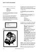
HOW TO USE THIS MANUAL This manual contains the following sections: - HOW TO USE THIS MANUAL SAFETY OPERATIONS MAINTENANCE PARTS LIST The HOW TO USE THIS MANUAL section will tell you how to find important information for ordering correct repair parts. Parts may be ordered from authorized Windsor dealers. When placing an order for parts, the machine model and machine serial number are important. Refer to the MACHINE DATA box which is filled out during the installation of your machine.
IMPORTANT SAFETY INSTRUCTIONS When using an battery powered appliance, basic precaution must always be followed, including the following: READ ALL INSTRUCTIONS BEFORE USING THIS MACHINE. To reduce the risk of fire, electric shock, or injury: Use only indoors. Do not use outdoors or expose to rain. Use only as described in this manual. Use only manufacturer’s recommended components and attachments.
HAZARD INTENSITY LEVEL The following symbols are used throughout this guide as indicated in their descriptions: HAZARD INTENSITY LEVEL There are three levels of hazard intensity identified by signal words -WARNING and CAUTION and FOR SAFETY. The level of hazard intensity is determined by the following definitions: WARNING - Hazards or unsafe practices which COULD result in severe personal injury or death.
SAFETY LABEL LOCATION NOTE: These drawings indicate the location of safety labels on the machine. If at any time the labels become illegible, promptly replace them. 86244300 PRV NO. 500955 WARNING LABEL 86252520 PRV NO.
TECHNICAL SPECIFICATIONS ITEM Nominal power Rated Voltage Rated Amperage Batteries Battery Compartment Dimensions Scrub Brush Motors - Disk Machine Scrub Brush Motors - Cylindrical Machine Vacuum Motor(s) Maximum flow rate of vacuum motor Maximum suction of vacuum motor Propelling Motor Mass (GVW) Weight empty without batteries Solution Control Solution capacity Recovery capacity Scrub brush diameter - Disk Machine Scrub brush diameter - Cylindrical Machine Scrub brush pressure Scrub brush speed - Disk Mach
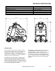
TECHNICAL SPECIFICATIONS ITEM Height Length Width without squeegee Width of squeegee - Disk Machine Width of squeegee - Cylindrical Machine Width of scrub path - Disk Machine Width of scrub path - Cylindrical Machine MEASURE 50.6 inches (1285 mm) 52.5 inches (1330 mm) 26.5 inches (670 mm) 32.7 inches (830 mm) 29 inches (737 mm) 24 inches (610 mm) 23 inches (585 mm) LENGTH WIDTH HEIGHT SPECIAL NOTES: The sound pressure level at the operator’s ear was measured to be 68 dBA.
HOW THIS MACHINE WORKS The Chariot® is a battery powered, self-propelled, hard floor scrubber intended for commercial use. The appliance applies a cleaning solution onto a hard floor, scrubs the floor with brushes, and then vacuums the soiled water back into the recovery tank. The machine's primary systems are the solution system, scrub system, recovery system, and operator control system. The function of the solution system is to store cleaning solution and deliver it to the scrub system.
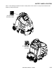
COMPONENTS 2 1 7 3 11 5 6 12 10 4 9 8 1. 2. 3. 4. 5. 6. Control Panel-Drive Control Panel-Scrub Control Housing Pedal Platform Rear Cover Tank 7. 8. 9. 10. 11. 12.
DRIVE CONTROLS 10 (Basic) 2 8 6 3 1 7 11 (Basic) 9 5 3-5 4 86037660 CHARIOT 11/09/06
DRIVE CONTROLS 1. 2. 3. 4. 5. 6. 1. Key Switch Emergency Stop/Brake Switch Directional Control Switch Throttle Pedal Operator Presence Pedal Speed Control Switch 7. 8. 9. 10. 11. Drive Reset Button Horn Button Steering Wheel Battery Discharge Indicator (Basic Only) Hour Meter (Basic Only) KEY SWITCH Controls the power for machine functions. To turn the machine power on, rotate key clockwise. To turn the machine off, rotate key counterclockwise.
DRIVE CONTROLS 6. SPEED CONTROL SWITCH Controls the maximum speed of the machine. There are two setting intended for scrubbing, speeds 1 and 2. Speed 3 is recommended for transport only, not scrubbing. To increase speed, press the top of the switch. To decrease speed, press bottom of the switch. Speeds can be adjusted at any time, whether machine is moving or not. Basic: The position of the switch indicates speed setting. Deluxe: The display indicates speed setting.
DRIVE CONTROLS 10A. BATTERY CHARGE LEVEL INDICATOR-BASIC Indicates the charge level of the batteries. The meter display is divided into 10 vertical bars. Bars illuminated on the far right indicate full charge. Bars flashing near the left side indicate the batteries should be recharged. Further operation of the machine could damage the machine or the batteries. When the machine is left overnight with less than a full charge, the display may initially indicate a full charge.
SCRUB CONTROLS-BASIC AND CYLINDRICAL 4 2 3 1 1. 2. 3-9 Squeegee Lift Lever Scrub Deck Actuator Switch 3. Brush Pressure Indicator 4.
SCRUB CONTROLS-BASIC-CYLINDRICAL 1. SQUEEGEE LIFT LEVER Raises and lowers the squeegee, and turns the vacuum motor on and off. To lower squeegee and start vacuum motor, lift the lever from its raised position. To raise squeegee and stop vacuum motor, lift the lever from its lowered position. 2. ACTUATOR SWITCH Raises and lowers the scrub deck, turns the scrub brush motors on and off, and adjusts the amount of brush/pad pressure to the floor.
SCRUB CONTROLS-DELUXE 5 1 4 1. One Touch Switch 2. Solution Control Switch 3. Brush Pressure Switch 3 2 4. Vacuum/Squeegee Switch 5. Display Toggle Switch 1. ONE TOUCH SWITCH This switch controls the scrub brushes and vacuum all in one touch. To start scrubbing, press the one touch switch. The brush drive motors will turn on, the scrub deck will lower to the "light scrub" position, the solution will flow at “one bar” rate, the squeegee will lower and the vacuum will turn on.
SCRUB CONTROLS-DELUXE 2. SOLUTION CONTROL SWITCH This switch controls the amount of solution flow to the scrub deck. The information screen will show the solution setting. There are 4 different flow settings. To increase the solution flow, press the bottom of the solution control switch (+). To decrease solution flow, press the top of the switch (-).
SCRUB CONTROLS-SQUEEGEE 1 2 2 DISK SCRUBBER CYLINDRICAL SCRUBBER 1. Squeegee Deflection Adjustment Knobs 2.
SCRUB CONTROLS-SQUEEGEE 1. SQUEEGEE DEFLECTION ADJUSTMENT KNOBS Adjusts the deflection along the entire length of the squeegee. To increase squeegee blade deflection, turn the two knobs at the ends of the squeegee counterclockwise. To decrease squeegee deflection, turn the two knobs at the ends of the squeegee clockwise. 2. SQUEEGEE PITCH ADJUSTMENT ROD (DISK SCRUBBER) Adjusts the deflection at the ends of the squeegee. To increase squeegee blade deflection at the ends, turn rod counterclockwise.
MACHINE OPERATION PRE-RUN MACHINE INSPECTION EMERGENCY STOP PROCEDURES Do a pre-run inspection to find possible problems that could cause poor performance or lost time from breakdown. Follow the same procedure each time to avoid missing steps. 1. Release the throttle pedal by lifting right foot. NOTE: See maintenance section for pre-run machine inspection checklist items. 3. If an electrical problem is suspected, push in emergency stop button.
MACHINE OPERATION FILLING SOLUTION TANK NORMAL SCRUBBING FOR SAFETY: Before leaving or servicing machine; stop on level surface, turn off machine and remove key. Plan the scrubbing pattern in advance. The longest track is around the perimeter of the area to be cleaned. For efficient operation, the runs should be the longest possible without turning, stopping, or raising or lowering scrub deck/squeegee. 1. Turn the machine power off. 2. Remove solution cover. 3.
MACHINE OPERATION TO BEGIN SCRUBBING PRIMING PUMP When operating the machine around people, pay close attention for unexpected movement. Use extra caution around children. If the solution system has gone dry or has been unused for a period of time, it may be necessary to follow the pump priming procedure. Flammable liquids and/or reactive metals can cause explosions or fire! Do not pick up. 1. Fill solution tank. 1. Place left foot on operator presence pedal.
MACHINE OPERATION TO STOP SCRUBBING DOUBLE SCRUB 1. BASIC AND CYLINDRICAL For floors which are heavily soiled or have thick accumulations of floor finish may not clean sufficiently with one pass. In these cases it will be necessary to double scrub. To double scrub, make the first pass over the surface being cleaned with the squeegee up, vacuum off, the solution on, Aqua-Mizer removed and brushes down.
MACHINE OPERATION SOLUTION TANK 1. Pull recovery drain hose out to expose the solution drain hose. 2. Pull the solution drain hose from under front of the tank. Unscrew the T-handle on plug enough to loosen plug, then lower hose in direction of drain. Slowly remove plug from drain hose. 3. Remove the solution tank cover. SOLUTION DRAIN HOSE RECOVERY DRAIN HOSE 4. Flush the solution tank out with clean water and run several gallons of clean water through systems.
NOTES: 86037660 CHARIOT 11/09/06 3-20
MAINTENANCE SERVICE SCHEDULE MAINTENANCE Check water level of batteries after charging; add distilled water if necessary. (Wet cell only) Check that dome and cover seal tightly. Visually check for damaged or worn tires. Check brushes or pads for proper installation. Check vacuum hose connections. Check that squeegee is securely attached and properly adjusted. Check for securely attached drain hoses, plug and cap. Check both pedals, brake and steering for proper operation.
MAINTENANCE-BATTERIES 1 2 3 4 5 6 1. 2. 3. Rear Cover Retainer Knob Rear Cover Battery Connector-Machine 4. 5. 6.
MAINTENANCE-BATTERIES BATTERIES (WET CELL ONLY) The batteries provide the power to operate the machine. The batteries require regular maintenance to keep them operating at peak efficiency. The machine batteries will hold their charge for long periods of time, but they can only be charged a certain number of times. To get the greatest life from the batteries, charge them when their charge level reaches 25% of a full charge. Use a hydrometer to check the charge level.
MAINTENANCE-BATTERIES CHECKING BATTERY SPECIFIC GRAVITY CHARGING BATTERIES Use a hydrometer to check the battery specific gravity. When servicing machine, avoid contact with battery acid. Batteries emit hydrogen gas. Explosion or fire can result. Keep sparks and open flame away. Keep covers open when charging. Battery Check Wear eye protection and protective clothing when working with batteries. Charge batteries in a well ventilated area. CHECKING GRAVITY A. Hydrometer B.
MAINTENANCE-BATTERIES 5. Replace the battery caps, and leave them in place while charging. 6. Unplug the battery connector from the machine. FOR SAFETY: When charging, connect the charger to the batteries before connecting the charger to the AC wall outlet. Never connect the charger to the AC wall outlet first. Hazardous sparks may result. 7. Plug the charger connector into the battery connector. Connect the charger AC plug to a wall outlet.
MAINTENANCE-SQUEEGEE 1 2 3 4 5 6 4 DISK SCRUBBER 1. 2. 3. 6 CYLINDRICAL SCRUBBER Squeegee Squeegee Deflection Adjustment Knobs Squeegee Level Indicator 4. 5. 6.
MAINTENANCE-SQUEEGEE SQUEEGEE BLADES TO REMOVE SQUEEGEE ASSEMBLY The front squeegee blade allows solution to pass through channels in the blade into the squeegee assembly while maintaining vacuum to provide lift. The front blade has four wear surfaces and can be rotated for extended life. The front blade should not require regular replacement under normal use. 1. With the squeegee in the up position, turn key switch “OFF”. The rear blade wipes the floor to a near dry condition.
MAINTENANCE-SQUEEGEE TO ADJUST SQUEEGEE PITCH TO ADJUST AMOUNT OF REAR SQUEEGEE DEFLECTION 1. Choose a smooth, level surface. Turn “ON” the key switch. Lower the squeegee and drive forward at least 2 feet (60cm.). 2. With the squeegee down, stop the machine. Do not allow machine to roll back. FOR SAFETY: Before leaving or servicing the machine; stop on level surface, turn off machine and remove key. 3. Determine the differences, if any, in deflection of the squeegee blade between each end and the middle.
MAINTENANCE-SCRUB BRUSHES SCRUB BRUSHES FINISHED FLOORS There are four different types of brushes available to cover applications from cleaning heavily soiled floors to polishing. A pad driver is also available to take advantage of the many cleaning pads on the market. Please refer to the following to assist in selecting the proper brush or pad for the work at hand. Nylon bristles are used in a variety of applications on coated or uncoated surfaces.
MAINTENANCE-SCRUB DECK – DISK 4 3 1 2 5 6 1. Scrub deck Aqua-Mizer™ 2. Aqua-Mizer™ retainer knob 3. Scrub deck skirt 4. Scrub deck skirt stop 5. Scrub brush motor 6.
MAINTENANCE-SCRUB DECK - DISK Do not use a pressure washer to clean around the brush motors. Use tap pressure only. BRUSH MOTOR CARBON BRUSH REPLACEMENT TO REPLACE SCRUB BRUSH MOTORS 1. Scribe alignment mark on motor barrel to motor cap. Remove two bolts. 1. With the scrub deck in the raised position, disconnect brush motor wiring connector from harness. 2. Remove end cap from motor. NOTE: Motors contain two wave washers in cap. Do not lose these. 2.
MAINTENANCE-SCRUB DECK - DISK SCRUB DECK ACTUATOR ADJUSTMENT FOR SAFETY: Before leaving or servicing machine, stop on a level surface. Turn off machine. The actuator will need to be adjusted when replaced. To adjust the actuator: 1. Remove the two screws that secure actuator spring plate and pull actuator barrel from stud on actuator spring bracket. 2. Remove clevis pin from upper bracket of actuator. 3. Disconnect actuator from wiring harness. 4. Reverse steps to install. 1.
MAINTENANCE-SCRUB DECK - CYLINDRICAL 6 7 1 4 1. 2. 3. 4. 4-13 4-13 Hopper Blade side squeegee Side squeegee adjustment knob Scrub brush motor 2 3 5 5. Scrub deck lift actuator 6. Side squeegee removal knob 7.
MAINTENANCE-SCRUB DECK - CYLINDRICAL SCRUB HEAD-CYLINDRICAL SCRUB BRUSH REPLACEMENT The dual cylindrical scrub head is designed to eliminate debris that may be caught in the squeegee while scrubbing. Water is applied to the first scrubbing brush turning in a clockwise rotation when viewed from the right of operator’s side of machine. The first brush scrubs dirt and debris between the brushes.
MAINTENANCE-SCRUB DECK - CYLINDRICAL DUMPING HOPPER ADJUSTMENT OF INDIVIDUAL BRUSHES The removable hopper is located behind the rear scrub brush. If the hopper becomes full, it will not accept any more debris. Loosen knob on left side squeegee and swing open. Remove the hopper by sliding it out from the operator’s left side of the machine. The hopper can then be dumped from the top. Flush the hopper clean with running water. The brush pattern is adjusted from the motor side only of both brushes. 1.
MAINTENANCE-SCRUB DECK - CYLINDRICAL Do not use a pressure washer to clean around the brush motors. Use tap pressure only. BRUSH MOTOR CARBON BRUSH REPLACEMENT TO REPLACE SCRUB BRUSH MOTORS 1. Scribe alignment mark on motor barrel to motor cap. Remove two bolts. 1. With the scrub deck in the raised position, disconnect brush motor wiring connector from harness. 2. Remove end cap from motor. NOTE: Motors contain two wave washers in cap. Do not lose these. 2. Remove side squeegee assembly. 3.
MAINTENANCE-SCRUB DECK - CYLINDRICAL ACTUATOR SCRUB DECK REMOVAL/REPLACEMENT SCRUB DECK ACTUATOR ADJUSTMENT FOR SAFETY: Before leaving or servicing machine, stop on a level surface. Turn off machine. 1. Lower scrub deck. 2. Disconnect spring assembly from actuator slide link. 3. Remove the clevis pin retaining the top of the acutator. 4. Remove slide link and actuator as an assembly by removing the two bolts connecting them to the deck through the bushings. 5.
MAINTENANCE-CIRCUIT PROTECTION 2 1 1. CIRCUIT BREAKERS (BASIC PANEL SHOWN) Circuit breakers interrupt the flow of power in the event of an electrical overload. When a circuit breaker is tripped, reset it by pressing the exposed button. If a circuit breaker continues to trip, the cause of the electrical overload should be found and corrected. 2. FUSE (DELUXE ONLY) The fuse is a one-time circuit protection device designed to stop the flow of electrical current in the event of an electrical overload.
MAINTENANCE-SOLUTION STRAINER & PUMP - DISK MODELS 1 5 2 6 3 4 1. Solution Strainer-Coarse 2. Solution Strainer-Fine 3. Pump 4-19 4. Pump Mounting Plate 5. Solenoid Valve 6.
MAINTENANCE-SOLUTION STRAINER & PUMP-CYLINDRICAL MODELS 1 2 6 1. Solution Strainer-Coarse 2. Solution Strainer-Fine 3. Pump 3 4 5 4. Solenoid Valve 5. Jets 6.
MAINTENANCE-SOLUTION STRAINER & PUMP 1. 3. SOLUTION STRAINER-COARSE Located in bottom of tank. The coarse strainer protects the finer strainer from large debris. If the fine strainer is clean and the pump and solenoid valve are not working, then check the coarse strainer for debris. Drain the solution tank and clean the coarse strainer. To remove the strainer, rotate the strainer counterclockwise. Cleanout the debris from wire mesh and re-assemble. 2.
MAINTENANCE-VACUUM & FLOAT SHUT-OFF 1 2 1. 2.
MAINTENANCE-VACUUM & FLOAT SHUT-OFF RECOVERY TANK FLOAT SHUT-OFF When water is no longer being vacuumed from the floor and the vacuum fan is operating, the ball float has engaged. The vacuum motor will not vacuum water with recovery tank full. The recovery tank must be drained. 1. The float shut-off screen can be cleaned in or out of the machine. 2. To clean the float shut-off while it is inside the machine wipe material off screen then rinse. Check that the ball is also clean and moves freely. 3. 4.
MAINTENANCE-DRIVE MOTOR & BRAKE 1. 2. 3.
MAINTENANCE-DRIVE MOTOR & BRAKE To disengage brake: ELECTRIC PARKING BRAKE ENGAGEMENT FOR SAFETY: Before leaving or servicing machine, stop on a level surface, turn off machine and remove key. Electric Brake Engagement This machine is equipped with an electric parking brake. The brake automatically engages and keeps the machine from moving whenever the operator steps off the platform or when emergency stop is engaged.
MAINTENANCE-DRIVE MOTOR & BRAKE DRIVE MOTOR CARBON BRUSH REPLACEMENT 5. Install new brush and reinstall connecting screw and lead. Do not use a pressure washer to clean around the motors. Use tap pressure only. 6. When all new brushes are installed. Place all in retracted position, held into brush holder by spring tension. FOR SAFETY: Before leaving or servicing machine, stop on a level surface, turn off machine and remove key. 7. Carefully replace brush cap. Reinstalling: 1.
MAINTENANCE-BAG REPLACEMENT REMOVING BAG REPLACING BAG 1. Disconnect batteries and make sure parking brake is not overridden. 1. Install mandrel in bottom of bag. 2. Under left front side of machine loosen hose clamp on recovery dump hose. Do not remove hose. 2. Place new bag in tank making sure hole for strainer basket is oriented properly. 3. Remove Dome and set aside 4. Remove Float cage, loosen screw on elbow and remove elbow. 3. Angle mandrel and bag into tank fitting toward front of machine.
MAINTENANCE-TRANSPORTING PUSHING MACHINE PREPARATION FOR LOADING /UNLOADING TRAILER The machine may be pushed for short distances at speeds not to exceed 5 mph. Be careful to avoid damaging machine. The machine may be pushed by hand from the rear. NOTE: To avoid damage caused by regenerative voltage, disconnect traction motor before towing or pushing machine. MACHINE TIE-DOWNS There are two tie points located at front and each side of foot box frame and two at the front side of frame.
MACHINE TROUBLESHOOTING PROBLEM No power to machine Little or no propel ERROR CODE DELUXE CAUSE Battery disconnected Emergency shut-off activated Check all battery cable connections Reset Battery cables corroded Main fuse blown (Deluxe Only) Clean connections Replace fuse Faulty key switch Replace switch Low battery charge Charge batteries Machine turned on with pedal not in neutral position Allow pedal to return to neutral.
MACHINE TROUBLESHOOTING PROBLEM Vacuum motor does not run, or runs slowly CAUSE ERROR CODE DELUXE Circuit breaker tripped (Basic) Faulty vacuum circuit or switch SOLUTION Reset circuit breaker 7700 Squeegee will not go up/down Faulty circuit or actuator (Deluxe) Faulty cables or pulleys Poor scrubbing performance Debris caught in scrub brushes Check wires, connections and switch Replace brushes, check commutator Check wires, connectors and actuator Repair/replace cables or pulleys Remove debris
MACHINE TROUBLESHOOTING – DELUXE CONTROLLER FAULT CODES ERROR CODE DELUXE PROBLEM None LCD display on, but incomplete 0A01 0204 Power down error Memory corrupt All 080_ codes Throttle wiring All 140 _ Codes All 310_ Codes Possible short circuit of motors, auxiliary outputs (headlight, recycle pump, or backup alarm), wiring or damaged controller 7500 LCD module communications timeout 7501 LCD module settings corrupt All 760_ Codes Brush motor or brush circuit fault All 770_ Codes Vacuum mot
MACHINE TROUBLESHOOTINGCONTROLLER FAULT CODES PROPEL CIRCUIT BOARD TROUBLESHOOTING Curtis 1228 LED DIAGNOSTICS- Basic and Cylindrical During normal operation, with no faults present, the status LED is steadily on. If the controller detects a fault, the status LED provides two types of information. First, it displays a slow flash (2 Hz) or a fast flash (4 Hz) to indicate the severity of the fault. Slow-flash faults are self-clearing; as soon as the fault is corrected, the vehicle will operate normally.
MACHINE TROUBLESHOOTINGCONTROLLER FAULT CODES LED CODE 3,1 PROGRAMMER LCD DISPLAY PROC/WIRING FAULT EXPLANATION POSSIBLE CAUSE HPD fault present for >10 sec. 1. Misadjusted throttle. 2. Broken throttle pot or throttle mechanism. 3,2 BRAKE ON FAULT brake On fault 1. Electromagnetic brake driver shorted. 2. Electromagnetic brake coil open. 3,3 PRECHARGE FAULT precharge fault 1. Low battery voltage. 2. KSI and throttle turned on at same time. 3,4 BRAKE OFF FAULT brake Off fault 1.
NOTES: 86037660 CHARIOT 11/09/06 4-32