Operating Instructions (ENG) MODEL : CMPS 10070050 CMPSR 10070080 FROM SN: 1000170681 Read instructions before operating the machine.
MACHINE DATA LOG/OVERVIEW MODEL _______________________________________ DATE OF PURCHASE __________________________ SERIAL NUMBER ______________________________ SALES REPRESENTATIVE # _____________________ Copyright 2003 Windsor Industries, Printed in USA YOUR DEALER Name: __________________________________________________________________________________________________ Address: _______________________________________________________________________________________________ Phone Number: ________________
TABLE OF CONTENTS Machine Data Log/Overview.........................1 Table of Contents..........................................2 HOW TO USE THIS MANUAL How to use this Manual.................................1-1 SAFETY Important Safety Instructions ........................2-1 Hazard Intensity Level. .................................2-2 Grounding Instructions..................................2-3 Safety Label Location. ..................................2-4 OPERATIONS Technical Specifications. ............
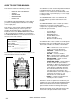
HOW TO USE THIS MANUAL This manual contains the following sections: - - HOW TO USE THIS MANUAL SAFETY OPERATIONS MAINTENANCE PARTS LIST The HOW TO USE THIS MANUAL section will tell you how to find important information for ordering correct repair parts. Parts may be ordered from authorized Windsor dealers. When placing an order for parts, the machine model and machine serial number are important. Refer to the MACHINE DATA box which is filled out during the installation of your machine.
IMPORTANT SAFETY INSTRUCTIONS When using an electrical appliance, basic precaution must always be followed, including the following: READ ALL INSTRUCTIONS BEFORE USING THIS MACHINE. This machine is for commercial use. ! WARNING: To reduce the risk of fire, electric shock, or injury: Connect to a properly grounded outlet. See Grounding Instructions. Do not leave the machine unattended. Unplug machine from outlet when not in use and before maintenance or service. Do not allow machine to be used as a toy.
HAZARD INTENSITY LEVEL The following symbols are used throughout this guide as indicated in their descriptions: HAZARD INTENSITY LEVEL There are three levels of hazard intensity identified by signal words -WARNING and CAUTION and FOR SAFETY. The level of hazard intensity is determined by the following definitions: ! WARNING WARNING - Hazards or unsafe practices which COULD result in severe personal injury or death.
GROUNDING INSTRUCTIONS THIS PRODUCT IS FOR COMMERCIAL USE ONLY. ELECTRICAL: In the USA, this machine operates on a standard 15 amp 115V, 60 Hz, A.C. power circuit. The amp, hertz, and voltage are listed on the data label found on each machine. Using voltages above or below those indicated on the data label will cause serious damage to the motors.
SAFETY LABEL LOCATION NOTE: These drawings indicate the location of safety labels on the Compass™. If, at any time, the labels become illegible contact your Windsor representative for prompt replacement. WARNING LABEL 86242230 PRV NO.
TECHNICAL SPECIFICATIONS ITEM Electrical Electric Pump Motor Solution Pump Electric Vacuum Motor Waterlift Solution Capacity DIMENSION/CAPACITY 115V, 12A, 60HZ 1/3hp, 1725rpm 500psi (34 bars), Axial plunger 2stage, 1.25hp (2.80m3/min.) 82 in. (208 cm) 29 gallons (111L) Recovery Capacity Wheels - Front (2) - Rear (2) Dimensions – Weight (CMPS) Dimensions – Weight (CMPSR) Dimensions – Length (CMPS) Dimensions – Length (CMPSR) Dimensions - Height Dimensions - Width Power Cable 19 gallons (70L) 6 in. dia.
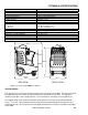
HOW THE MACHINE WORKS The Compass™ is a multi-functional cleaning machine intended for commercial use. The appliance applies chemical at low pressure and uses high pressure to clean with. Then the soiled water is vacuumed back into the recovery tank. The machine's primary systems are the clean water system, recovery system, chemical system and pressure washer system. The function of the clean water system is to store clean water and deliver it to the available tools.
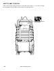
COMPONENTS 1. 2. 3. 4. 5. 6. Control Panel Solution Tank Solution Tank Lid Solution Tank Drain Hose Solution Tank Fill Hose Recovery Tank 7. Recovery Tank Lid 8. Recovery Tank Drain Hose 9. Chemical Siphon Caps 10. Electrical Cord 11. High Pressure Hose Storage 12.
CONTROLS 7 2 8 3 4 1 5 6 1. 2. 3. 4. 5. Solution Accessory Tool Hook-Up Vacuum Accessory Tool Hook-Up Pump Switch Vacuum Switch Chemical Selector and Metering Valve 3-4 6. Caster Lock 7. Vacuum Circuit Breaker 8.
CONTROLS 1. SOLUTION ACCESSORY TOOL HOOK-UP Used for various auxiliary-cleaning tools. 2. VACUUM ACCESSORY TOOL HOOK-UP To use accessory tool, remove hose from vac shoe and attach to accessory tool adaptor. 3. PUMP SWITCH Turns the pump On and Off. 4. VACUUM SWITCH Turns the vacuum motor On and Off. 5. CHEMICAL SELECTOR AND METERING VALVE Meters the amount of chemical being dispensed and selects between chemical A or B and turn off. 6. CASTER LOCK Locks the wheels in place to keep the machine from moving.
OPERATIONS FILLING THE MACHINE Do not put defoamer, solvents spotter or prespray chemicals in the solution tank. 3. Attach the adapter cap and intake hose to the CompassTM Chemical bottle. Refer to the CompassTM Chemical Label for the desired dilution. 1. Always use gloves and eye protection. Never spray solution towards people. 4. Position the CompassTM machine in the door way, lock front casters. Start at furthest point in the room and work towards the door. 2.
OPERATIONS 7. Use brush or grout tool for heavy soiled areas. 10. Store and secure hoses and tools neatly. 8. Turn Chemical off. Pressure clean by rinsing surfaces at high pressure. 11. Drain machine at proper disposal areas. Use pressure gun to rinse and clean recovery tank. 9. Use Squeegee or Gulper tool to remove standing water. 12. When using dry filter, gently remove and wash with water after every use. Allow to dry before re-using.
OPERATIONS Care must be exercised in the use of all chemicals. Chemicals are poisonous and can pose a health risk. Read and follow manfacturers instructions regarding dangers and correct usages. The internal parts of the pump used in the machine are suitable for use with most carpet cleaning chemicals. But they are susceptible to chemical attack from some cleaning substances, such as hydrocarbon solvents and chlorinated bleaches. These non-compatible materials are not of the type used for carpet cleaning.
MAINTENANCE 1. 2. 3. 4. Float Shut-Off Strainer Circuit Breakers Vacuum Motor 5. Pump 6.
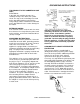
MAINTENANCE 1. FLOAT SHUT-OFF The float shut-off is located inside the recovery tank. The purpose of the float shut-off is to notify the user that the recovery tank is full. Remove daily and clean any debris for maximum airflow. 2. STRAINER The strainer is located on the lower right side between the front and rear wheels. The strainer protects the check valve and pump from debris. If there is little or no solution flow to the ground, check the stainer for debris.
MAINTENANCE 4. VACUUM MOTOR (Refer to vacuum group in the parts section of manual). ONLY QUALIFIED MAINTENANCE PERSONNEL ARE TO PERFORM THE FOLLOWING REPAIRS. VACUUM MOTOR REPLACEMENT 1. Turn off all switches and unplug machine. 2. Remove recovery tank. 3. Remove the 5 screws holding the vacuum motor cover to the solution tank. 4. Locate the vacuum motor wires and disconnect at the connector. 5. Remove the vacuum motor. 6. Reverse process to install.
MAINTENANCE 5. PUMP 6. REGULATING UNLOADER ONLY QUALIFIED MAINTENANCE PERSONNEL ARE TO PERFORM THE FOLLOWING REPAIRS. ONLY QUALIFIED MAINTENANCE PERSONNEL ARE TO PERFORM THE FOLLOWING REPAIRS. SOLUTION PUMP REPLACEMENT 1. Turn off all switches and unplug machine. 2. Tilt machine back so bottom is exposed. 3. Remove the 6 screws that fasten the frame to the solution tank. 4. Remove the solution hoses from the fittings on the pump. 5. Reverse process to install. UNLOADER REPLACEMENT 1.
MAINTENANCE PERIODIC MAINTENACE DAILY/REGULAR MAINTENANCE Twice a month, flush a white vinegar solution (one quart vinegar to two gallons of water) or antibrowning solution (mixed as directed) through the machine. This will prevent build-up of alkaline residue in the system. If spray jets become clogged, remove the spray tips, wash them thoroughly, and blow dry. Before making any adjustments to the machine, disconnect the power cord from the electrical source. 1.
TROUBLESHOOTING PROBLEM Loss of Power Electrical shock CAUSE SOLUTION Dead electrical circuit Faulty power cord GFCI breaker is tripped Equipment not grounding Receptacle not grounded Check building circuit breaker or fuse box.
NOTES: CMPS 86290230 02/22/07 4-7
CONTROLS 5-1 CMPS 86290230 02/22/07
CONTROLS REF PART NO. PRV NO.
RECOVERY TANK 5-3 CMPS 86290230 02/22/07
RECOVERY TANK REF PART NO. PRV NO.
SOLUTION TANK 5-5 CMPS 86290230 02/22/07
SOLUTION TANK REF PART NO. PRV NO.
VACUUM 20 21 19 22 28 14 GROUND WIRE 27 (26) 27 10 9 23 11 16 18 12 13 24 14 GROUND WIRE 4 26 15 25 5-7 CMPS 86290230 02/22/07
VACUUM REF PART NO. PRV NO.
WHEELS & FRAME 5-9 CMPS 86290230 02/22/07
WHEELS & FRAME REF PART NO. PRV NO. QTY 1 2 3 4 5 6 7 8 9 86202280 86271380 86010670 86277040 86014710 86276940 86232620 86078800 86270830 89252 57196 87029 70781 70758 18043 620001 57023 2 2 18 10 1 8 2 1 8 DESCRIPTION SERIAL NO. FROM NOTES: WHEEL, 12” BLK CNTRD HUB NUT, 1/2 PUSH-ON DOME CAP WASHER, 5/16 FLAT SS SCR, 5/16-18 X 1/2 HHCS SS NP FRAME, PUMP/WHEEL MNT SCR, 1/4-20 X 3.5 HHCS SS NP CASTER, 6” DIA X 4.
PUMP 15 14 16 13 11 13 9 8 17 12 10 5 7 18 19 6 4 3 2 1 5-11 CMPS 86290230 04/20/07
PUMP REF PART NO. PRV NO.
PUMP 1 2 3 4 5 6 5-13 CMPS 86290230 04/20/07
PUMP REF PART NO. PRV NO. QTY DESCRIPTION 1 86014510 - 1 PUMP ASM, 500 PSI 120V CMPS 2 3 4 5 6 86004370 86002390 86264940 86010650 86270990 39547 20063 27051 87018 57090 1 1 2 4 4 HOSE ASM, 1.5 BLK VAC X 21 CLAMP, 1.75 WORM GEAR X .312 CABLE TIE, 11.38 UL/CSA WASHER, #10 X 9/16 OD NUT, 10-32 HEX NYLOCK SS CMPS 86290230 04/20/07 SERIAL NO.
TOOLS - STANDARD 1 2 5 3 4 6 17 13A 13B 7 8 16 9 10 11 5-15 CMPS 86290230 04/20/07
TOOLS - STANDARD REF PART NO. PRV NO.
VAC HOSE RACK – CMPSR ONLY 5-17 CMPS 86290230 04/20/07
VAC HOSE RACK - CMPSR REF PART NO. PRV NO. QTY DESCRIPTION 1 2 3 4 5 6 7 86240630 86276600 86006590 86275210 86270250 86005680 86068180 49499 70696 70088 70384 03-000133 57047 140710 1 3 2 2 2 2 1 HOSE RACK SCR, #10 X 3/4 PTHSMS SS SCR, 10-32 X 1/2 PPHMS SS NP SCR, 1/4-20 X ½ PHTR BLK DL CLAMP, 1/4X1/4 BLT VIN DP NUT, ¼-20 HEX NYLOCK BRACKET, TOP HOSE RACK CMPS 86290230 04/20/07 SERIAL NO.
WIRING – SCHEMATIC PUMP MOTOR BLK GRN/YEL WHT POWER POWER CORD INCLUDED W/PUMP MOTOR GRN/YEL WHT BLK PANEL GROUND 86015000 WHT GRN/YEL BLK 86014950 PUMP MOTOR GROUND GRN/YEL GRN/YEL GRN/YEL BLK BLK WHT WHT WHT WHT WHT 86014960 VACUUM CIRCUIT BREAKER 7 4 8 1 88951 5 2 CMPS 86290230 04/20/07 7 4 5-19 VACUUM SWITCH 5 VACUUM MOTOR 8 1 880420 BLK BLK 2 6 3 GRN/YLW BLK BLK 6 86014970 3 VAC MOUNT GROUND 880420 BLK PUMP CIRCUIT BREAKER PUMP SWITCH
SUGGESTED SPARE PARTS PART NO. PRV NO. 86241930 86256090 86202070 86135320 86028720 86002010 86230210 86001940 86241930 86290270 86290280 86290390 86290400 86290410 47419 730262 360-04B 140687 53266 14942 14832 14635 47419 - DESCRIPTION SERIAL NO.
TOOLS- DRY CLEAN OPTION 5-21 CMPS 86290230 04/20/07
TOOLS – DRY CLEAN OPTION REF PART NO. PRV NO. QTY 1 2 3 4 86236130 86257630 86257700 86286550 34410 02474 02485 47422 1 1 1 REF DESCRIPTION SERIAL NO.
TOOLS- LOW FLOW SPRAY GUN OPTION 2 1 6 3 4 5 5-23 CMPS 86290230 04/20/07
TOOLS – LOW FLOW SPRAY GUN OPTION REF PART NO. PRV NO. QTY 1 2 3 4 5 6 86258920 86290390 86005580 86246040 86241690 86041290 84186 1 1 1 1 1 REF 56012 51389 44078 47427 DESCRIPTION SERIAL NO.
TOOLS- GROUT CLEANER OPTION 5-25 CMPS 86290230 04/20/07
TOOLS – GROUT CLEANER OPTION REF PART NO. PRV NO. QTY DESCRIPTION 1 2 3 4 5 6 7 8 9 10 11 12 13 86200820 86247720 86194160 86240190 86090230 86241700 86006590 86088740 86230820 86270990 86070460 86276290 86000480 270-11A 56032 11-800133 39639 87015 44079 70088 02476 140653 57090 140652 70626 47431 1 1 1 2 4 2 4 1 2 4 2 4 REF NIPPLE, 1/8 FPT QD MALE BRASS NIPPLE, 1/8 CLOSE TEE, 1/8 BR HOSE, 1/8 MPT X 1/4 FPT X 12L WASHER, 9/16 ID X 1.
TOOLS- HIGH PRESSURE WAND OPTION 5-27 CMPS 86290230 04/20/07
TOOLS – HIGH PRESSURE WAND OPTION REF PART NO. PRV NO. QTY DESCRIPTION 1 2 3 4 5 6 7 8 9 86005580 86240210 86274410 86258950 86240200 86200810 86257680 86270990 86041300 56012 39641 70195 84189 39640 270-11 02480 57090 47432 1 1 1 1 1 1 1 1 REF NIPPLE, 1/4 FPT QD HOSE, 1/8 MPT X 1/4 MPT X 7 L SCR, 10-32 X 1.
TOOLS- CARPET TOOL OPTION 5-29 CMPS 86290230 04/20/07
TOOLS – CARPET TOOL OPTION REF PART NO. PRV NO. QTY DESCRIPTION 1 2 3 4 5 6 86200820 86240220 86197360 86090230 86241710 86284550 270-11A 39642 31016 87015 44080 02484 1 1 1 4 1 - NIPPLE, 1/8 FPT QD MALE BRASS HOSE, 1/8 MPT X 1/4 FPT X 12L ELBOW, 1/4 NPT STREET WASHER, 9/16 ID X 1.06 OD SS JET, 1/4 H-VV 11003 TOOL, CARPET CLEANER CMPS 86290230 04/20/07 SERIAL NO.
STORAGE BAG-OPTION 5-31 CMPS 86290230 04/20/07
STORAGE BAG-OPTION REF PART NO. PRV NO. QTY 1 86283390 47423 1 DESCRIPTION SERIAL NO.
CHEMICAL LOCK-OPTION 5-33 CMPS 86290230 04/20/07
CHEMICAL LOCK-OPTION REF PART NO. PRV NO. QTY 1 86070520 140660 1 DESCRIPTION SERIAL NO.
NOTES 5-35 CMPS 86290230 04/20/07