OPE~UIION Floor Scrubber WIN- 1 INDUSTRIES, INC., 1351 W. Stanford Ave.
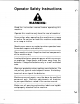
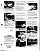
Operator Safety Instructions Read the instruction manual before operating this machine. Operate this machine only from the rear of machine. Use caution when operating the machine on a ramp or incline. Do not turn or leave this machine unattended on a ramp or incline. Machine can cause an explosion when operated near flammable vapors and materials. Store machine inside. Keep the electrical components of the machine dry. Lead acid batteries generate gases which can cause an explosion.
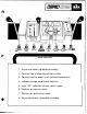
I‘ ‘I SQUEEGEE LIFT LEVER SOLUTION CONTROL LEVER MAIN SWITCH BATTERY CONOlTlON LIGHT SOLUTION “ON” LIGHT VACUUM BRUSH SCRUB DECK “ON” LIGHTED “ON” LIGHTED LIFT LEVER SWITCH SWITCH OPERATOR CONTROL HANDLE 1. Raises and lowers squeegee assembly. 2. Controls flow of cleaning solution to floor. 3. Controls electric power to all switched components. 4. Indicates charge condition of batteries. 5. Light “ON” indicates solution valve is open. 6. Switches on vacuum motor. 7. Switches on brush drive motor.
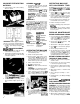
MACHINE PREPARATION CLEANING SOLUTlON BATTERIES 1. Fill machine with hot water and add cleaning chemical at the proportion noted on the container. 1. Install batteries and connect battery cables as shown. CAUTION: Always use a low sudslng cleaning chemical desi ned for use In automatic hard surface ?loor scrubbers. CAUTION: To avoid possible distortion of polyethylene solution/ recovery tanks. DO NOT USE WATER TEMPERATURE THAT EXCEEDS 150’F (65°C).
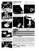
3. Keep the battery electrolyte at th$ correct level - approximately 114 below bottom of filler tube of each cell. Distilled water should be added, as needed, AFTER charging cycle. 4. Check motor brushes. When worn to 318” replace both brushes. WARNING: Do not allow electrolyte level to drop below the tops of the plates. SERVICING THE COMPACT SCRUBBER ’ CAUTION: 3. Connect the “DC” charger plug to the connector on the machine.
SCRUB DECK/BRUSH MOTOR 1. Remove (4) screws holding motor shroud. 4. Disconnect motor leads from terminal block. 5. Remove (4) screws holding brush motor to scrub deck. 7. Squeegee tracking can be controlled by adjustin tension of squeegee springs. NOT%: Position recovery hose as shown before making adjustments. 2. Remove batteries and squeegee assembly. Lay machine on side. 3. Remove center screw holding drive plate. Slide drive plate off motor shaft. Brush Motor 6.
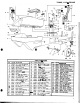
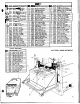
TANKS, VAC & FRAME ' 27 39 12 It TANKS, VAC 6 FRAME KEY PART NO. DESCRIPTION 1 70020 2 61181 3 87090 4 70010 5 34188 6 57119 7 18027 8 70266 9 70327 10 27266 11 09010 12 89068 13 73437 14 27408 15 70119 16 03058 17 75152 18 50363 19 27416 20 51138 21 75153 Scr, 1/4-20 x 112 HHMS Panel, Rear Washer, 1/4 Flat Scr, 1/4-20 x 1.
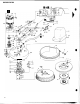
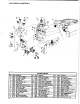
SCRUB DECK 0 24 A0 ‘74 \ // 8 8
SCRUB DECK I KEY I t I I PARTNO. DESCRIPTION KEV PUTNO. DESCRIPTION I KEY PARTNO. DESCRIPTION I 1A 73425 Strap Asm, PTC17 Bumper 1B 73465 Strap Asm, PTC20 Bumper 2 87090 Washer, 1/4 ID x 3/4 Flat 3 48012 Knob, Adjustment 4A 14676 Bumper, PTC17 Brush Shroud 48 14571 Bumper, PTC20 Brush Shroud 5A 02162 Pad Driver, 16" Ylw Pad Lock 58 02156 Pad Driver Asm. 16" Weighted 5C 02098 Pad Driver, 18" Blk Pad Lock 5D 02169 Pad Driver Asm, 18" Weighted 6 70304 Scr, W14x 1.
ELECTRICAL CONTROLS , 26 27 28 29 14 10 13
MECHANICAL CONTROLS 14 /" 28 I 37 LJ '\ @ --24 13 41 I . 34 30 A - 3 I -31/36 1- 32 I 12 1 t '8 22 MECHANICAL CONTROLS I(EI 1 2 3 4 5 6 7 8 9 10 11 12 13 14 PART NO. DESCRIPTION 29151 66068 67226 73236 27413 66121 66116 70020 27401 70025 57030 51125 67138 48030 Door. Battery Compartment Pin, 118 x 5/8 Roll Rod, Battery Door Lock Spring, 1.
SQUEEGEE EL SQUEEOEE LIFT MECHANISM Frame r 4? I I - Frame I 4 SQUEEGEE & SQUEEGEE LIFT MECHANISM KEY 1 2 3 4 5 6 7 8 9 10 11A 116 12 13A 138 14 15 16 17 12 PART NO. OESCRIPTION KEY PART NO.
AUXILIARY PUMP MODEL 3 20 28 PLUMBING 27 STANDARD MODEL Note: Plumbing iIlustrated with machine laying on right side.
TROUBLE-SHOOTING GUIDE PROBLEM PROBABLE CAUSE CORRECTIVE ACTION No power. Battery cables corroded at battery terminals. Faulty main switch. 1. Clean battery cable clamps and battery terminals. 2. Check voltage at points A and B. Voltage should be 22/26 VDC. 1. Check voltage at points B and C. Voltage should be 22/26 VDC. 2. Turn main switch on and check voltage at points B and D. Voltage should be 22/26 VDC. If no voltage remove leads and check switch for continuity.
POWER SWITCH \ WIRING DIAGRAM SOLUTION SWITCH SOLUTION LIGHT BATTERY LEVEL LIGHT VACUUM MOTOR VACWM/BRUSH SWITCH al: e [ PUMP SWITCH IOPTIONAL) PUMP MOTOR (OPTIONAL) I i CHARGER CONNECTION PUMP Pump Assembly 65019 I Pump Repair Kit 47020 I I r a I I Pump Motor 53188 I 0 Plug 66017 Housing 41010 Cover 27057 Base - 62053 15