Carpet Extractor Operating instructions (ENG) MODELS: COMDU 10086120 COMXDU 10086140 COMDUX 10086160 COMXDUX 10086180 Read these instructions before using the machine.
Machine Data Label OVERVIEW The Commodore Duo is a battery powered carpet extractor intended for commercial use. The Commodore Duo applies a cleaning solution onto a carpeted floor, sweeps and scrubs the carpet with two counter-rotating brushes and then vacuums the soiled water back into the recovery tank. Warranty Registration Thank you for purchasing a Windsor product. Warranty registration is quick and easy. Your registration will allow us to serve you better over the lifetime of the product.
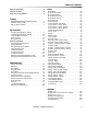
Table of Contents Machine Data Label . . . . . . . . . . . . . . . . . . . . . . . . . . 2 Table of Contents . . . . . . . . . . . . . . . . . . . . . . . . . . . 3 How To Use This Manual . . . . . . . . . . . . . . . . . . . . . 4 Safety IMPORTANT SAFETY INSTRUCTIONS . . . . . . . . . 5 Hazard Intensity Level . . . . . . . . . . . . . . . . . . . . . . . 6 Safety Label Locations . . . . . . . . . . . . . . . . . . . . . . . 7 Operations Technical Specifications - Basic . . . . . . . . . . . . . . . .
How To Use This Manual The OPERATIONS section is to familiarize the operator with the operation and function of the machine. This manual contains the following sections: • • • • • HOW TO USE THIS MANUAL SAFETY OPERATIONS MAINTENANCE PARTS LIST The MAINTENANCE section contains preventive maintenance to keep the machine and its components in good working condition.
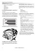
Safety IMPORTANT SAFETY INSTRUCTIONS When using an battery powered appliance, basic precaution must always be followed, including the following: READ ALL INSTRUCTIONS BEFORE USING THIS MACHINE. To reduce the risk of fire, electric shock, or injury: Use only indoors. Do not use outdoors or expose to rain. Use only as described in this manual. Use only manufacturer's recommended components and attachments.
Safety Hazard Intensity Level The following symbols are used throughout this guide as indicated in their descriptions: There are three levels of hazard intensity identified by signal words - WARNING and CAUTION and FOR SAFETY. The level of hazard intensity is determined by the following definitions: WARNING - Hazards or unsafe practices which COULD result in severe personal injury or death. CAUTION - Hazards or unsafe practices which could result in minor personal injury or product or property damage.
Safety Safety Label Locations NOTE: These drawings indicate the location of safety labels on the machine. If at any time the labels become illegible, promptly replace them. SOLUTION WARNING 86244300 (PRV NO. 500955) PINCH CAUTION 86243830 (PRV NO. 500663) FRONT PANEL CAUTION 86013310 BATTERY CAUTION 86252520 (PRV NO.
Notes: 8 86292200 COMMODORE DUO
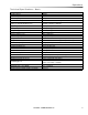
Operations Technical Specifications - Basic ITEM Nominal Power Rated Voltage Rated Amperage Batteries Battery Compartment Dimensions Propelling Motor Mass (GVW) Weight Empty Without Batteries Solution Control Spray Pump Pressure Solution Capacity Spray Jets - Interim Spray Jets - Extraction Recovery Capacity Vacuum Motors Scrub Brush Diameter Scrub Brush Motor Scrub Brush Pressure Scrub Brush Speed Tires Foundation Pressure Maximum (Transport) Speed Scrubbing Speed Frame Construction Minimum Aisle U-Turn Wi
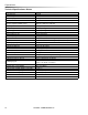
Operations Technical Specifications- Deluxe ITEM Nominal Power Rated Voltage Rated Amperage Batteries Battery Compartment Dimensions Propelling Motor Mass (GVW) Weight Empty Without Batteries Solution Control Spray Pump Pressure Solution Capacity Spray Jets - Interim Spray Jets - Extraction Recovery Capacity Vacuum Motors Scrub Brush Diameter Scrub Brush Motor Scrub Brush Pressure Scrub Brush Speed Tires Foundation Pressure Maximum (Transport) Speed Scrubbing Speed Frame Construction Minimum Aisle U-Turn Wi
Operations Technical Specifications ITEM MEASURE Height Length Width Width of scrub path 43 54 27 20 inches (1100 mm) inches (1400 mm) inches (700 mm) inches (500mm) WIDTH LENGTH SPECIAL NOTES: The sound pressure level at the operator's ear was measured to be 69.5dBA. This was a nearfield, broadband measurement taken in a typical industrial environment on a tile floor. This appliance contains no possible source of impact noise. The instantaneous sound pressure level is below 63 Pa.
Operations How This Machine Works Deluxe Only The Machine is a battery powered, self-propelled Carpet Maintainer and Carpet Extractor intended for commercial use. The function of the chemical injection system is to deliver the appropriate chemical into the solution system to be applied to the carpet. The chemical injection system consists of the "A" chemical tank, "B" chemical tank, chemical selector valve, chemical pump, and the mixing sector.
Operations Components 9. Solution Drain Hose 1. Control Panel-Drive/Scrub 10. Vacuum Shoes 2. Front Cover 11. Chemical Tank "A" (Deluxe) 3. Solution Tank 12. Chemical Tank "B" (Deluxe) 4. Recovery Tank 13. Accessory Vacuum Port (Deluxe) 5. Solution Fill Cover 14. Accessory Water Port (Deluxe) 6. Recovery Dome 15. Accessory Port Cover (Deluxe) 7. Scrub Deck 16. Switch, Chemical Prime and flush for "A" and "B" Systems (Deluxe) 8.
Operations 5 2 4 3 1 6 7 Drive Controls 1. Key Switch 2. Reverse Switch 3. Throttle Switches 4. Speed Control Knob 5. Battery Discharge Indicator 6. Hour Meter 7.
Operations 1. Key Switch Controls the power for machine functions. To turn the machine power on, rotate key clockwise. To turn the machine off, rotate key counterclockwise. 2. Reverse Button Controls the direction of travel of the vehicle. To travel in reverse, press the button and press either of the throttle switches. To travel forward, release the button are press either of the throttle switches. 3. Throttle Switches Propel the vehicle with the speed control knob setting selected.
Operations 2 3 1 Scrub Controls 1. Solution Pump Switch 2. Solution Pump Indicator 3.
Operations 1. Solution Pump Switch Controls power to the spray pump. If the throttle is in neutral, or reverse control button is in reverse position, the flow is automatically interrupted. This feature prevents application of solution without scrubbing it into carpet. 2. Solution Pump Indicator Light The solution pump indicator light is illuminated green when the pump is on. 3.
Operations Scrub Deck Rotary Switch (Deluxe) Raises and lowers the scrub deck, and turns the scrub brush motors on and off, and controls the solution solenoids. For interim/pre-spray "A" mode, rotate the function knob to the "A" position. The "A" chemical will be drawn from its tank and delivered to the solution system. The scrub deck will lower and the scrub motor will turn on and the interim/ pre-spray solenoid will open and spray will flow through the jets.
Operations Machine Operation Emergency Stop Procedures 1. Release both the throttle switches. Pre-Run Machine Inspection Do a pre-run inspection to find possible problems that could cause poor performance or lost time from breakdown. Follow the same procedure each time to avoid missing steps. NOTE: See maintenance section for pre-run machine inspection checklist items. Starting Machine NOTE: Perform pre-run machine check before operating machine.
Operations Filling Solution Tank Normal Scrubbing FOR SAFETY: Before leaving or servicing machine; stop on level surface, turn off machine and remove key. Plan the scrubbing pattern in advance. 1. Turn the machine power off. 2. Remove the front cover and the solution fill lid. 3. Fill the solution tank with clean water. (See the Technical Specifications chart for exact capacity). The water must not be hotter than 140° F (60°C) to prevent damage to the tank. 4.
Operations To Begin Scrubbing To Stop Scrubbing When operating the machine around people, pay close attention for unexpected movement. Use extra caution around children. 1. Turn machine power on. 2. Position rotary switch to the position matching the process to be preformed, and the chemical that was added to the solution tank or chemical tank (Deluxe), either interim or interim/pre-spray (Deluxe) or extraction/cleaning. 3.
Operations Emptying And Cleaning Chemical Tanks And System (Deluxe) 1. Turn off machine and remove front cover. 2. Park the machine next to a floor drain. The tanks are located at the front of the machine. 3. Remove the cap and straw from each chemical bottle and install the closed caps. 4. Remove the tanks by lifting off the solution fill tower. SOLUTION DRAIN HOSE 5. The chemical can remain in the tank or be disposed of properly. Remove one cap at a time and properly dispose of chemical.
Notes 86292200 COMMODORE DUO 23
Maintenance Service Schedule Maintenance Check water level of batteries after charging; add distilled water if necessary. Check brushes for proper installation. Check for securely attached drain hose, plug and cap. Check that solution fill lid seals tightly Visually check for damaged or worn tires. Check all throttle, direction and speed controls for proper operation. Observe spray pattern and clean jets if necessary. Prime chemical system for 30 seconds for each chemical. Clean brushes and check wear.
Maintenance 1. Battery Connector 5. "Y" Tube 2. Battery Connector 6a. Recovery Hose - Basic 3. Batteries 6b. Recovery Hose - Deluxe 4.
Maintenance Batteries (Wet Cell Only) The batteries provide the power to operate the machine. The batteries require regular maintenance to keep them operating at peak efficiency. When servicing machine, avoid contact with battery acid. The machine batteries will hold their charge for long periods of time, but they can only be charged a certain number of times. To get the greatest life from the batteries, charge them when their charge level reaches 25% of a full charge.
Maintenance Checking Battery Specific Gravity Charging Batteries Use a hydrometer to check the battery specific gravity. When servicing machine, avoid contact with battery acid. Batteries emit hydrogen gas. Explosion or fire can result. Keep sparks and open flame away. Keep covers open when charging. Wear eye protection and protective clothing when working with batteries.
Maintenance 6. Replace the battery caps, and leave them in place while charging. Changing Batteries 7. Unplug the machine connector from the battery. Stop the machine in a clean area next to the charger. Turn off machine. FOR SAFETY: When charging, connect the charger to the batteries before connecting the charger to the AC wall outlet. Never connect the charger to the AC wall outlet first. Hazardous sparks may result.
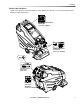
Maintenance 1 2 4 3 Scrub Deck 1. Scrub deck lift actuator 2. Scrub brush motor 3. Scrub brushes 4.
Maintenance Scrub Head Scrub Brushes The dual cylindrical scrub head is designed to scrub chemical into the carpet. The two counter rotating brushes raise the pile of the carpet, giving it a lush groomed appearance. Scrub Brush Removal The scrub brushes are removed from the right side of the machine. 1. Raise the scrub deck to the storage position. 2. Pull out on the bottom of the retaining clip. Maintenance Scrub brushes should be exchanged front to back every 50 hours to ensure even wear.
Maintenance Scrub Motor Brush Motor Carbon Brush Replacement 1. Scribe alignment mark on motor barrel to motor cap. Remove two bolts. Do not use a pressure washer to clean around the brush motors. Use tap pressure only. To Replace Scrub Brush Motor 2. Remove end cap from motor. NOTE: Motors contain two wave washers in cap. Do not lose these. 1. With the scrub deck in the lowered position, remove the deck cover and disconnect brush motor wiring connector from harness. 3.
Maintenance Actuator Scrub Deck Removal/ Replacement Scrub Deck Actuator Adjustment FOR SAFETY: Before leaving or servicing machine, stop on a level surface. Turn off machine. To adjust the actuator: The actuator will need to be adjusted when replaced. 1. Lower scrub deck. Remove the front cover and raise recovery tank. 2. Disconnect electrical connector. 3. Remove the clevis pin retaining the bottom of the acutator. 4. Remove the clevis pin retaining the top of the acutator. 5.
Maintenance DELUXE ONLY 1 Circuit Protection 1. Circuit Breakers 30 Amp. Protects the vacuum motor. Circuit breakers interrupt the flow of power in the event of an electrical overload. When a circuit breaker is tripped, reset it by pressing the exposed button. If a circuit breaker continues to trip, the cause of the electrical overload should be found and corrected 30 Amp. Protects the vacuum motor. 22 Amp. Protects the scrub brush motor. 25 Amp. Protects the propel motor. 3 Amp.
Maintenance 1 2 3 4 5 Solution Strainer & Pump-Basic 1. Pump 4. Jets- Interim 2. Solution Strainer 5. Jets-Extraction 3.
Maintenance Solution Strainer Jets The solution strainer is located on the front of the machine under the front cover. The strainer protects the pump, solenoid valve and jets from debris. If there is little or no solution flow to the ground, check the strainer for debris. Clean the solution strainer. To remove the strainer, turn the bottom part of the strainer counterclockwise until the bottom is separated. Clean out the debris from the wire mesh and the bowl and reassemble.
Maintenance 1 2 7 6 4 5 3 3 Solution Strainer & Pump-Deluxe 1. Pump 5. Jets-Extraction 2. Solution Strainer 6. A-B Chemical Valve 3. Solenoid Valves 7. Chemical pump 4.
Maintenance Pump Jets The pump is located on underside of the recovery tank. The pump delivers solution from the tank to the scrub deck. The two sets of jets are located in front of the scrub deck. To repair or replace pump: 1. Remove bracket assembly from the bottom side of the recovery tank. The jets spray cleaning solution onto the carpet. The spray pattern should be checked regularly and if jets become clogged they should be cleaned or replaced immediately. To clean jets: 2.
Maintenance A-B Chemical Pump & Chemical Pump 1. The chemical tank "A" holds either encapsulating interim chemical or pre-spray chemical. Tanks should be cleaned weekly. Extra chemical should be stored using the blank cap instead of the straw cap. 2. The chemical tank "B" hold the deep extraction chemical. The tank should be cleaned weekly. Extra chemical should be stored using the blank cap instead of the straw cap. 3.
Maintenance 1 2 3 2 Drive Assembly 1. Drive Assembly 2. Grease Points 3.
Maintenance Drive Assembly Drive Motor Carbon Brush Replacement Do not use a pressure washer to clean around the motors. Use tap pressure only. FOR SAFETY: Before leaving or servicing machine, stop on a level surface, turn off machine and remove key. 1. Disconnect batteries from machine. 2. Disconnect the electrical connection to the traction motor. 3. Remove brush cap. 4. Release brush from spring tension. Remove screw connecting brush wire lead to brush holder. Clean brush holder to insure free movement.
Maintenance 5 6 4 2 1 2 3 Vacuum 1. Vacuum Shoes 2. Vacuum Glides 3. Vacuum Shoe Retainer Knobs 4. "Y" Tube 5. Float Ball And Screen 6.
Maintenance Vacuum Shoes Recovery Tank Float Shut-Off The dual offset vacuum shoes are designed to extract soiled solution from the carpet. The plastic vacuum shoe glides minimize wear to flooring. Maintenance When water is no longer being vacuumed from the floor and the vacuum fan is operating, the ball float has engaged. The vacuum motors will not vacuum water with recovery tank full. The recovery tank must be drained. The vacuum shoes should be removed and cleaned daily to ensure maximum recovery.
Maintenance To Repair Or Replace Vacuum Motor(s) Vacuum Motor Carbon Brushes 1. Remove the front cover, drain the recovery tank. 2. Raise the recovery tank and safely engage the prop rod latch. End Cap 3. Disconnect electrical connector from the vacuum motor(s) and connecting hoses. 4. Unbolt the bracket and vacuum motor assembly and remove from tank. Carbon Brushes 5. Remove the vacuum motor from the bracket. 6. Reverse steps to install. Make sure the gaskets fit and seal properly as you reassemble.
Maintenance Transporting Machine Preparation For Loading /Unloading Trailer Pushing Machine The machine may be pushed for short distances at speeds not to exceed 5 mph. Be careful to avoid damaging machine. The machine may be pushed by hand from the rear. Before loading or unloading machine from trailer, remove vacuum shoes to eliminate interference. Scrub head must be in the up position before loading.
Maintenance Machine Troubleshooting PROBLEM No power to machine Little or no propel CAUSE Battery disconnected Battery cables corroded Faulty key switch Low battery charge Machine turned on with propel trigger not in neutral position Tripped circuit breaker Controller overheated Loose motor connection Faulty throttle circuit or potentiometer Faulty brake circuit Machine does not Faulty speed control circuit or potentiometer change speeds Forward speed only Faulty forward/reverse switch Reverse speed only
Notes: 46 86292200 COMMODORE DUO
Parts PARTS 86292200 COMMODORE DUO 47
Brush Deck 48 86292200 COMMODORE DUO
Brush Deck REF PART NO. PRV NO.
Brush Deck Actuator 50 86292200 COMMODORE DUO
Brush Deck Actuator REF PART NO. 1 2 3 4 5 6 7 8 86008670 86248970 86011800 86091930 86010670 86276780 86279130 86278910 PRV NO. QTY 80606 81406 141037 87029 70728 87083 87003 2 2 1 1 2 2 2 1 DESCRIPTION SERIAL NO. FROM NOTES COTTER, 3/8 RING PIN, CLEVIS 3/8 X 2.00 PLTD ACTUATOR, 36 VDC 2.
Brush Deck Motor 52 86292200 COMMODORE DUO
Brush Deck Motor REF PART NO. PRV NO. QTY DESCRIPTION SERIAL NO.
Brush Deck Mounting 54 86292200 COMMODORE DUO
Brush Deck Mounting REF PART NO. 1 2 3 4 5 6 7 8 9 86277030 86228990 86270830 86010670 86071800 86088110 86259420 86277130 86296180 PRV NO. QTY 70780 09153 57023 87029 141001 730443 87232 70795 - 2 2 8 8 1 1 2 2 1 DESCRIPTION SERIAL NO. FROM NOTES SCR, 5/16-18 X 1.25 CARRIAGE SS BEARING, FLNGD, .314ID X .502OD NUT, 5/16-18 HEX NYLOCK SS WASHER, 5/16 FLAT SS BRKT, BRUSH DECK PIVOT STRAP, SHROUD LATCH WASHER, THRUST .51 ID X 1 OD SCR, 5/16-18X1.
Brush Deck Shroud 8 7 9 1 2 1 3 4 5 6 56 86292200 COMMODORE DUO
Brush Deck Shroud REF PART NO. 1 2 3 4 5 6 7 8 9 86161800 86273950 86270920 86062320 86012190 86012200 86279190 86274520 86006400 PRV NO. QTY 46-802531 70056 57049 270156 87095 70233 67380 1 2 2 1 2 1 1 1 2 DESCRIPTION SERIAL NO. FROM NOTES LATCH, CONCEALED KEEPER SCR, 6-32 X 1/2 PPHMS SS NUT, 6-32 NUT NYLOCK SS COVER, DECK FOAM SPACER, SHROUD, 5/16 T FOAM SPACER, SHROUD, 3/4 TS WASHER, #10 FLAT PLTD SCR, #10 X 3/8 PH HI-LO PLT RIVET, 5.
Brush Deck Lift 58 86292200 COMMODORE DUO
Brush Deck Lift REF PART NO. PRV NO. QTY DESCRIPTION SCR, 5/16-18 X 2.5 FHSC SS SPACER, .74 OD X .391 ID X 1.0 L NYL BEARING FLG .377 ID X .502 OD X .500 WASHER, 5/16 FLAT SS NUT, 5/16-18 HEX NYLOCK SS SCR, 1/4-20 X 4.5" CARRIAGE SS BEARING, FLNGD, .314ID X .502OD LIFT RAM LEFT, REAR SCR, 5/16-18 X 1.0 FHCS SS SPRING, COMP .97D X 2.5L X .12W BUSHING, .377ID X .627OD X .63 NUT, 1/4-20 HEX NYLOCK THIN SS WASHER, 1/4" ID X 1.
Control Handle 9 3 2A 2B 4 10 5 6 1 8 60 7 86292200 COMMODORE DUO
Control Handle REF PART NO. 1 2A 2B 3 4 5 6 7 8 9 10 86277050 86238730 86238740 86240990 86254920 86277070 86231480 86277060 86257230 86004120 86004130 PRV NO. QTY 70782 38307 38308 41431 730153 70784 140504 70783 730125 38312 38313 4 1 1 2 2 2 2 4 2 - DESCRIPTION SERIAL NO. FROM NOTES SCR, 5/16-18 X 3/4 SHCS SS HANDLE, LEFT HANDLE, RIGHT HOUSING, BUTTON SPRING, COMP .24OD X 1.25X.018 SCR, 4-40 X 5/8 PPHMS BUTTON, PROPEL SCR, 8.
Control Panel-Lower-Basic 62 86292200 COMMODORE DUO
Control Panel-Lower-Basic REF PART NO. 1 2 3 4 5 6 7 8 9 10 11 12 13 14 15 16 17 18 19 86005530 86002010 86008900 86229770 86295570 86273880 86012910 86270850 86255900 86237900 86251360 86007190 86002000 86001920 86001910 86005810 86230080 86250210 86250160 PRV NO. QTY 54154 14942 80845 140805 70030 57026 73538 35278 67166 72161 14717 14607 14606 57245 141044 66873 66321 1 2 2 1 1 2 1 2 4 3 1 1 1 1 1 2 1 1 1 DESCRIPTION SERIAL NO.
Control Panel - Upper - Basic 10 1 9 2 3 4 5 6 7 8 64 86292200 COMMODORE DUO
Control Panel - Upper - Basic REF PART NO. 1 2 3 4 5 6 7 8 9 10 86006230 86012670 86255900 86005810 86251360 86014690 86257180 86257150 86026010 86242110 PRV NO. QTY DESCRIPTION 66193 73538 57245 67166 72207 72197 82522 48088 1 1 2 2 1 1 1 1 1 1 POTENTIOMETER, 5 K OHMS METER. BATTERY, PG TRUE CHARGE STANDOFF, 3-32 X 5/8 HEX NYL NUT, 1/4-20 HEX NYLOCK SS RELAY, 36VDC 100A SWITCH, ROTARY CAM SWITCH, MOMENTARY, DPDT, WHITE SWITCH, SPDT P-BUTTON LIGHT ASM, INDICATOR KNOB, .90 OD X .
Control Panel - Lower - Deluxe 66 86292200 COMMODORE DUO
Control Panel - Lower - Deluxe REF PART NO. 1 2 3 4 5 6 7 8 9 10 11 12 13 14 15 16 17 18 86005530 86002010 86008900 86229770 86295570 86273880 86012910 86270850 86255900 86237900 86251360 86007190 86002000 86001920 86001910 86005810 86230080 86250160 PRV NO. QTY 54154 14942 80845 140805 70030 57026 73538 35278 67166 72161 14717 14607 14606 57245 141044 66321 1 2 3 1 1 2 1 2 4 3 1 1 1 1 2 2 1 1 DESCRIPTION SERIAL NO.
Control Panel - Upper - Deluxe 10 1 9 5 2 3 4 5 7 6 11 13 12 3 8 68 86292200 COMMODORE DUO
Control Panel - Upper - Deluxe REF PART NO. 1 2 3 4 5 6 7 8 9 10 11 12 13 86006230 86012670 86255900 86005810 86251360 86014690 86257180 86257150 86026010 86242110 86251410 86300140 86254640 PRV NO. QTY DESCRIPTION 66193 73538 57245 67166 72207 72197 82522 48088 67506 82810 1 1 6 4 2 1 1 1 1 1 1 1 2 POTENTIOMETER, 5 K OHMS METER.
Control Panel Mounting 1 2 3 4 70 86292200 COMMODORE DUO
Control Panel Mounting REF PART NO. 1 2 3 4 86276290 86294250 86072110 86274290 PRV NO. QTY 70626 141056 70162 7 7 1 2 DESCRIPTION SERIAL NO. FROM NOTES SCR, #10 X 3/4 PPHST HI-LO BLK WASHER, .19 ID X .5 X .
Cover - Front 1 2 3 8 6 7 72 86292200 COMMODORE DUO 5 4
Cover - Front REF PART NO. 1 2 3 4 5 6 7 8 86271870 86010630 86270990 86290740 86278390 86006830 86062330 86010650 PRV NO. QTY 57290 87013 57090 73866 70386 270168 87018 4 4 2 2 2 2 1 2 DESCRIPTION SERIAL NO. FROM NOTES NUT, 1/4-20 HEX NYLOCK THIN SS WASHER, 1/4 ID X 5/8 OD SS NUT, 10-32 HEX NYLOCK SS BRKT, FRONT LATCH SPACER, 1/2" OD X .219 ID X 1/2" SCR, 10-32 X 1.
Decal 1 2 7 6 3 4 5 74 86292200 COMMODORE DUO
Decal REF PART NO. 1 2 3 4 5 6 7 86013270 86013310 86013670 86013680 86004970 86013320 86014330 PRV NO. QTY 50990 - 1 1 1 1 1 1 1 DESCRIPTION SERIAL NO.
Frame-Lower 1 3 4 2 5 6 76 86292200 COMMODORE DUO
Frame-Lower REF PART NO. 1 2 3 4 5 6 86276780 86010670 86091950 86092570 86271840 86293740 PRV NO. QTY 70728 87029 141053 34473 57285 - 2 8 1 1 8 2 DESCRIPTION SERIAL NO.
Frame-Upper 78 86292200 COMMODORE DUO
Frame-Upper REF PART NO. 1 2 3 4 5 6 7 86012890 86276780 86010670 86279580 86276490 86277460 86279630 PRV NO. QTY 70728 87029 87183 70670 70847 87212 1 4 7 2 5 2 2 DESCRIPTION SERIAL NO. FROM NOTES WELDMENT, FRAME MAIN SCR, 5/16-18 X 3/4 HHCS SS WASHER, 5/16 FLAT SS WASHER, 1/2 X 1" X 1/8" NYLON SCR, 5/16-18 X 5/8 HHCS SS SCR, 5/16-18 X 5/8 BSHCS SS WASHER, .344IDX1.13ODX.
Recovery Tank 80 86292200 COMMODORE DUO
Recovery Tank REF PART NO. 1 2 3 4 5 6 7 8 9 10 11 12 13 14 15 16 17 18 19 20 21 22 23 24 25 86274220 86003340 86246080 86014810 86004010 86199840 86227120 86293240 86002380 86012150 86240130 86292740 86290830 86238460 86270830 86013350 86276490 86005660 86002400 86237650 86089630 86004260 OPEN 86246070 86328980 PRV NO. QTY 70134 28062 51368 35274 090-12A 04095 20046 39560 36259 57023 70670 57033 20064 35219 78490 39472 51352 - 1 1 1 1 1 1 1 1 1 1 1 1 2 2 5 1 7 2 4 2 1 1 1 1 DESCRIPTION SERIAL NO.
Recovery Tank Handle - Basic 11 13 12 5 6 14 15 1 9 8 7 10 17 4 16 1 15 9 8 3 2 82 86292200 COMMODORE DUO
Recovery Tank Handle - Basic REF PART NO. 1 2 3 4 5 6 7 8 9 10 11 12 13 14 15 16 17 86276490 86277640 86290730 86226740 86010800 86276290 86011930 86010630 86271870 86013990 86217470 86222620 86008650 86291800 86010670 86290850 86010650 PRV NO. QTY 70670 70893 73215 87189 70626 87013 57290 270800 66891 80604 87029 87018 3 4 2 4 2 2 1 6 6 1 1 1 2 1 3 1 1 DESCRIPTION SERIAL NO. FROM NOTES SCR, 5/16-18 X 5/8 HHCS SS SCR, 1/4-20 X 3/4 PTHMS SS LATCH, FRONT COVER SPACER, 3/8 X .265 X 1/4 NYL WASHER, .
Recovery Tank Handle - Deluxe 84 86292200 COMMODORE DUO
Recovery Tank Handle - Deluxe REF PART NO. 1 2 3 4 5 6 7 8 9 10 11 12 13 14 15 16 17 18 19 20 21 22 23 24 25 26 27 28 29 30 31 32 33 34 35 36 86276490 86277640 86290730 86226740 86010800 86276290 86011930 86010630 86271870 86294880 86217470 86222620 86008650 86291800 86010670 86290850 86010650 86275470 86224770 86279170 86295160 86278910 OPEN 86293920 86295720 86270990 86197520 86217270 86200820 86002400 86240120 86007210 86005580 86197300 86247720 86200810 PRV NO.
Solution - Chemical Tanks - Deluxe 8 14 13 12 15 16 2 1 18 11 3 10 19 9 4 3 7 86 86292200 COMMODORE DUO 6 5
Solution - Chemical Tanks - Deluxe REF PART NO. 1 2 3 4 5 6 7 8 9 10 11 12 13 14 15 16 17 18 19 86012760 86001530 86233150 86197980 86011360 86233110 86197910 86295280 86274400 86297610 86019510 86295710 86293960 86295310 86236590 86088670 OPEN 86294860 86233090 PRV NO. QTY 40039 20042 40055 20018 40022 70194 75492 34448 75493 20016 1 2 3 1 1 1 1 2 4 1 1 1 1 1 2 1 1 1 DESCRIPTION SERIAL NO.
Solution Pump 20 28 18 25 13 25 12 11 10 24 1 9 DELUXE PUMP 26 2 7 8 24 7 -A- 3 24 -B- 9 6 5 -C24 4 24 -B11 10 12 13 14 29 15 16 30 31 18 17 19 24 20 21 31 -C- 25 -A- 23 24 BASIC PUMP 88 27 86292200 COMMODORE DUO 22
Solution Pump REF PART NO. 1 2 3 4 5 6 7 8 9 10 11 12 13 14 15 16 17 18 19 20 21 22 23 24 25 26 27 28 29 30 31 32 86006580 86292230 86012690 86240500 86010670 86276490 86001530 86012760 86005870 86136800 86197940 86006100 86010650 86270990 86197290 86200820 86247720 86197300 86290000 86197730 86197760 86197500 86197980 86011360 86233110 86233150 86233090 86010630 86197910 86240360 86005580 86197300 86247720 86200810 PRV NO.
Solution - Chemical Pump - Deluxe 1 2 12 3 5 -A-C- 4 13 -C- 16 14 13 10 -B- -B- 15 8 11 -A- 9 17 9 6 7 90 86292200 COMMODORE DUO
Solution - Chemical Pump - Deluxe REF PART NO. 1 2 3 4 5 6 7 8 9 10 11 12 13 14 15 16 17 86010670 86276490 86295370 86270830 86297820 86274290 86293970 86353090 86295810 86293720 86295290 86293880 86297460 86298040 86264860 86238490 86197400 PRV NO.
Solution -Chemical Valves - Deluxe 2 3 1 7 10 6 9 6 11 6 5 11 8 6 5 12 7 3 4 92 86292200 COMMODORE DUO
Solution -Chemical Valves - Deluxe REF PART NO. 1 2 3 4 5 6 7 8 9 10 11 12 86295260 86273980 86010650 86353090 86197750 86240610 86233090 86247720 86295650 86297830 86013030 86295550 PRV NO. QTY 70066 87018 78161 44104 20016 56032 - 1 4 8 4 2 5 5 2 1 1 2 1 DESCRIPTION SERIAL NO.
Solution Tank 94 86292200 COMMODORE DUO
Solution Tank REF PART NO. 1 2 3 4 5 6 7 8 9 10 11 12 13 14 15 16 17 18 19 20 21 22 23 24 25 26 27 28 29 30 31 86011820 86011810 86290370 86276760 86006860 86010650 86290830 86238460 86292730 86072200 86010670 86013700 86276490 86276070 86239630 86270830 86006560 86217540 86259410 86290190 86271840 86259910 86276380 86274720 86228990 86011630 86011490 86197040 86295730 86293700 86007020 PRV NO.
Spray Jets 96 86292200 COMMODORE DUO
Spray Jets REF PART NO. 1 2 3 4 5 6 7 8 9 10 11 12 13 14 15 16 86197400 86233090 86197640 86197750 86227200 86240610 86270830 86010670 86004570 86013200 86012550 86091880 86010820 86296310 86276070 86297030 PRV NO. QTY 31022 20016 40064 78161 04007 44104 57023 87029 44067 141019 87192 70593 - 2 6 4 2 1 2 3 2 4 2 2 1 4 1 1 1 DESCRIPTION SERIAL NO.
Spray Jet Valves - Basic 3 1 6 2 11 4 10 6 10 5 8 6 7 98 9 10 86292200 COMMODORE DUO
Spray Jet Valves - Basic REF PART NO. 1 2 3 4 5 6 7 8 9 10 11 86270830 86010670 86197400 86013030 86197750 86197520 86353090 86013070 86014250 86233090 86247720 PRV NO. QTY 57023 87029 31022 78161 40011 20016 56032 2 2 1 2 1 3 4 1 1 3 1 DESCRIPTION SERIAL NO. FROM NOTES NUT, 5/16-18 HEX NYLOCK SS WASHER, 5/16 FLAT SS ELBOW, 1/8NPT STREET VALVE, 36VDC SOLENOID, 1/8 FPT TEE, 1/8 NPT STREET RUN HOSEBARB, 1/8MPT X 1/4 DL SCR, 8-32 X 5/16 PPHMS SS BRACKET, DUO VALVE MOUNT ORIFICE, .052 ID, .
Spray Jet Valves - Deluxe 3 6 11 10 6 4 10 5 1 2 8 10 7 9 12 13 5 14 15 3 100 86292200 COMMODORE DUO
Spray Jet Valves - Deluxe REF PART NO. 1 2 3 4 5 6 7 8 9 10 11 12 13 14 15 86270830 86010670 86197400 86013030 86197750 86197520 86353090 86013070 86240610 86233090 86247720 86295290 86180670 86295300 86227200 PRV NO.
Wheel And Drive Assembly 102 86292200 COMMODORE DUO
Wheel And Drive Assembly REF 1 2 3 4 5 6 7 8 9 10 11 12 13 14 15 16 17 18 PART NO. PRV NO. 86315130 86288820 140592 86072100 141055 86270440 48008 86270830 57023 86079600 620138 86008710 80623 86277930 70119 86273750 70011 86277130 70795 86279640 87213 86010780 87162 86278940 87008 86226040 89278 86010670 87029 86177040 03-000149 86277030 70780 86316850 86277930 - QTY DESCRIPTION 1 1 2 4 2 2 8 2 3 4 2 2 2 4 1 1 2 4 TRANSAXLE, 36VDC BRUSH SET, TRANSAXLE 78434 CCL BRKT, CABLE GUARD KEY, 3/16 X 1.
Vacuum Shoe 7 6 19 16 4 17 3 18 19 13 12 14 9 8 20 18 17 10 15 1 12 11 2 5 104 86292200 COMMODORE DUO
Vacuum Shoe REF PART NO. PRV NO. QTY 1 2 3 4 5 6 7 8 9 10 11 12 13 14 15 16 17 18 19 20 86219150 86071990 86276650 86219690 86296540 86003010 86001480 86276070 86010770 86273740 86270830 86093610 86072020 86072010 86072000 86271870 86010630 86259420 86259400 86228920 39739 141027 70707 48080 27759 39315 70593 87143 70010 57023 620134 141030 141029 141028 57290 87013 87232 87205 09140 1 1 2 2 2 1 1 10 4 4 10 2 1 1 1 4 8 8 8 4 DESCRIPTION SERIAL NO. FROM NOTES: HOSE ASM, 1.
Vacuum Shoe 1 2 4 3 5 6 7 9 16 8 14 13 12 11 10 106 86292200 COMMODORE DUO 15
Vacuum Shoe REF PART NO. PRV NO. QTY 1 2 3 4 5 6 7 8 9 10 11 12 13 14 15 16 86006580 86075450 86237910 86237920 86237930 86237940 86237950 86259980 86275950 86293190 86296520 86310750 86296410 86302700 86296550 86296350 70085 27246 35279 35280 35281 35282 35283 85012 70568 - 10 1 1 1 1 1 1 1 4 3 1 1 1 10 1 1 DESCRIPTION SCR, 1/4-20 X 1/2 PPHMS SS COVER, VAC SHOE GASKET, VAC SHOE OUTER GASKET, 5.0 OD X 2.0 ID X .
Vacuum - Basic 108 86292200 COMMODORE DUO
Vacuum - Basic REF PART NO. PRV NO.
Vacuum - Deluxe 110 86292200 COMMODORE DUO
Vacuum - Deluxe REF PART NO. PRV NO.
Wiring-Battery-Basic 14 15 16 1A 1B 1C 1D 13 11 20 11 1B 5 A 19 18 2A 12 3 2B A 4 A 6 9 7 8 10 112 86292200 COMMODORE DUO
Wiring-Battery-Basic REF PART NO. PRV NO.
Wiring-Battery-Deluxe 114 86292200 COMMODORE DUO
Wiring-Battery-Deluxe REF PART NO. PRV NO.
Wiring-Control Panel-Basic 37/RED 40/BLK 49/PNK 34/YLW 31/BRN 33/PUR 36/WHT 50/PNK 38/YLW 6 7 35 43 /LT /WH -B LU T 31/BRN 32/BRN 29/BRN 30/BRN 12/WHT-RED 11/RED 3/GRN 4/WHT-GRN 5/WHT-BLU 30/BRN 53/RED 52/RED 1/YLW 56/YLW 55/BLK 54/BLK 56/YLW 52/RED 23/RED 49/PNK 45/GRN 46/GRN 3/GRN 44/WHT-GRN 4/WHT-GRN 32/BRN 47/BLK 48/WHT 55/BLK 6/WHT-YLW 57/WHT-YLW 53/RED 57/WHT-YLW 28/RED 27RED 51/LT-BLU 2/LT-BLU 48/WHT 12/WHT-RED 50/PNK 6/WHT-YLW 2/BLU 12 1 1 1 2 3 46/GRN 42/LT-BLU 26/RED 51/BLU
Wiring-Control Panel-Basic REF PART NO. PRV NO. QTY 1 2 86261210 86261250 29204 29273 3 2 3 86013210 - 1 DESCRIPTION SERIAL NO.
Wiring - Control Panel - Deluxe 118 86292200 COMMODORE DUO
Wiring - Control Panel - Deluxe REF PART NO. PRV NO. QTY 1 2 86261210 86261250 29204 29273 4 3 3 86295170 - 1 DESCRIPTION SERIAL NO.
Wiring - Main Harness-Basic 120 86292200 COMMODORE DUO
Wiring Main Harness-Deluxe 86292200 COMMODORE DUO 121
Wiring Diagram - Basic 40/BLK 35/WHT 43/LT-BLU 12/WHT-RED 22/RED 24/WHT-RED 86269300 PRV 88868 KEY SWITCH 16/RED EMERGENCY STOP 17/BLK 46/GRN 4/WHT-GRN 51/BLU 41/RED 44/WHT-GRN 10/WHT 9/BLK 24/WHT-RED 25/RED 35/WHT 26/RED 25/RED 37/RED 21/WHT-RED 43/LT-BLU 34/YLW 33/PUR 86261210 PRV 29204 86261250 PRV 29273 15/RED 16/RED TRACTION 25A BRUSH RELAY 22/RED 23/RED 86261210 PRV 29204 18/BLK 15/RED 26/RED 8/RED BRUSH 22A 86261250 PRV 29273 19/RED 28/RED 13/RED VAC MOTOR 30A 59/BLK 29
Wiring Diagram - Deluxe 86292200 COMMODORE DUO 123
Hose Diagram-Basic SOLUTION TANK ACCESSORY PORT 86282320 (49") PRV NO. 39710 86240280 (8") PRV NO. 39711 86290860 (51") BYPASS VALVE STRAINER FILTER SOLUTION PUMP 86281310 (8.8") PRV NO. 39326 ORIFICE RESTRICTOR 86280760 (6") PRV NO. 151-47B 86290870 (10") VALVE VALVE 86280760 (6") PRV NO.
Hose Diagram-Deluxe 86292200 COMMODORE DUO 125
Suggested Spare Parts PART NO. PRV NO.
Options OPTIONS 86292200 COMMODORE DUO 127
Battery Cart 1 2 3 6 8 22 4 5 1 7 2 9 10 11 1 12 19 16 21 8 2 6 BATTERY CART LATCH LINKAGE ASEMBLY 20 3 13 18 15 1 13 14 17 1 16 BATTERY CART LATCH ASEMBLY 128 86292200 COMMODORE DUO
Battery Cart REF PART NO. PRV NO.
Battery Cart - Latch And Latch Linkage 1 2 6 3 4 LATCH LINKAGE 5 8 17 9 7 10 16 15 10 14 11 LATCH 12 13 130 86292200 COMMODORE DUO
Battery Cart - Latch And Latch Linkage REF PART NO. PRV NO. QTY 1 2 3 4 5 6 7 8 9 86008860 86292870 86292860 86008670 86292850 86249060 86298200 86273820 86010630 80808 80606 82061 70019 87013 1 1 1 2 1 1 4 2 2 10 86259400 87205 6 11 86259420 87232 2 12 86228900 09138 2 13 14 15 16 17 86005810 86011270 86275460 86292980 86255060 57245 70481 73426 2 1 4 2 1 DESCRIPTION SERIAL NO. FROM NOTES: PIN, CLEVIS 3/8 X 5.
Battery Cart - Tray 5 6 4 1 2 3 132 86292200 COMMODORE DUO
Battery Cart - Tray REF PART NO. PRV NO. QTY 1 2 3 4 5 6 86005810 86278150 86281060 86275870 86008760 86011530 57245 70117 89265 70556 80682 - 10 8 8 2 1 1 DESCRIPTION SERIAL NO. FROM NOTES: NUT, 1/4-20 HEX NYLOCK SS SHOULDER BOLT, 5/16 OD X 1.0 L WHEEL, BATTERY TRAY SCR, 1/4-20 X 1.
Battery Exchange Option 1 2 1 3 2 4 6 7 8 5 11 12 9 10 134 86292200 COMMODORE DUO
Battery Exchange Option REF PART NO. PRV NO. QTY 1 2 3 4 5 6 7 8 9 10 11 12 86276780 86010670 86290220 86011300 86011280 86278150 86290510 86292830 86292820 86290500 86292840 86226780 70728 87029 70117 73044 8 8 1 1 1 2 4 1 1 2 1 1 DESCRIPTION SERIAL NO. FROM NOTES: SCR, 5/16-18 X 3/4 HHCS SS WASHER, 5/16 FLAT SS PLATE, OPTION, CART LATCH GUIDE, BATTERY TRAY, RIGHT GUIDE, BATTERY TRAY, LEFT SHOULDER BOLT, 5/16 OD X 1.0 L WASHER, THRUST .315 ID X .
Emergency Stop-Option 1 136 86292200 COMMODORE DUO
Emergency Stop-Option REF PART NO. PRV NO. QTY 1 2 86007180 86299300 72160 88868 1 1 DESCRIPTION SWITCH, EMERGENCY STOP WIRE, 16" RED/18 STRIPX STRIP 86292200 COMMODORE DUO SERIAL NO.
Serial Numbers REF. NO.