Commodore Duo Carpet Extractor Operating Instructions (ENG) MODELS: COMDU 10086120 COMXDU 10086140 COMDUX 10086160 COMXDUX 10086180 From Serial Number (Ref No. 1*) * See Serial Number page or call manufacturer.
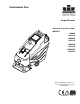
Machine Data Label Overview The Commodore Duo is a battery powered carpet extractor intended for commercial use. The Commodore Duo applies a cleaning solution onto a carpeted floor, sweeps and scrubs the carpet with two counter-rotating brushes and then vacuums the soiled water back into the recovery tank. Warranty Registration Thank you for purchasing a Kärcher North America product. Warranty registration is quick and easy.
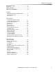
Table of Contents Machine Data Label . . . . . . . . . . . . . . . . . . . . . . . . . . 2 Overview . . . . . . . . . . . . . . . . . . . . . . . . . . . . . . . . . . 2 Table of Contents . . . . . . . . . . . . . . . . . . . . . . . . . . . 3 How To Use This Manual . . . . . . . . . . . . . . . . . . . . . 4 Safety IMPORTANT SAFETY INSTRUCTIONS . . . . . . . . . 5 Hazard Intensity Level . . . . . . . . . . . . . . . . . . . . . . . 7 Safety Labels . . . . . . . . . . . . . . . . . . . . . . . . . . . . .
How To Use This Manual This manual contains the following sections: • • • • • How to Use This Manual Safety Operations Maintenance Suggested Spare Parts List The SAFETY section contains important information regarding hazardous or unsafe practices of the machine. Levels of hazards are identified that could result in product damage, personal injury, or severe injury resulting in death. The OPERATIONS section is to familiarize the operator with the operation and function of the machine.
Safety IMPORTANT SAFETY INSTRUCTIONS When using this machine, basic precaution must always be followed, including the following: READ ALL INSTRUCTIONS BEFORE USING THIS MACHINE. To reduce the risk of fire, electric shock, or injury: Use only indoors. Do not use outdoors or expose to rain. Use only as described in this manual. Use only manufacturer's recommended components and attachments.
Safety MESURES DE SÉCURITÉ IMPORTANTES Lors de l’utilisation d’un appareil à batteries, il est nécessaire de respecter systématiquement des mesures de sécurité de base, comme suit : PRENEZ NOTE DE TOUTES CES MESURES AVANT D’UTILISER CETTE MACHINE. Pour réduire les risques d’incendie, de chocs électriques, ou de blessures : N’utiliser cette machine qu’en intérieur. Ne jamais l’utiliser à l’extérieur ou dans la pluie. N’utiliser cette machine que comme décrit dans le présent manuel.
Safety Hazard Intensity Level The following symbols are used throughout this guide as indicated in their descriptions: There are three levels of hazard intensity identified by signal words -WARNING and CAUTION and FOR SAFETY. The level of hazard intensity is determined by the following definitions: WARNING - Hazards or unsafe practices which COULD result in severe personal injury or death. CAUTION - Hazards or unsafe practices which could result in minor personal injury or product or property damage.
Safety Les symboles ci-dessous sont utilisés à travers ce manuel comme illustré dans leurs descriptions : DEGRÉS DE RISQUES EN CAS DE DANGER Il existe trois degrés de risques identifiés par les termes signalétiques –AVERTISSEMENT et ATTENTION et POUR VOTRE SÉCURITÉ. Le degré de risque est défini de la manière suivante: AVERTISSEMENT - Dangers ou méthodes dangereuses qui POURRAIENT provoquer de graves blessures ou entraîner la mort.
Safety Safety Labels These drawings indicate the location of safety labels on the machine. If at any time the labels become illegible, promptly replace them. EMPLACEMENT DE L'ÉTIQUETTE DE SÉCURITÉ REMARQUE : Ces dessins indiquent l'emplacement des étiquettes de sécurité sur la machine.
Notes 10 86400200 Operators Manual - Commodore Duo
Operations Technical Specifications - Basic ITEM Nominal Power Rated Voltage Rated Amperage Batteries Battery Compartment Dimensions Propelling Motor Mass (GVW) Weight Empty Without Batteries Solution Control Spray Pump Pressure Solution Capacity Spray Jets - Interim Spray Jets - Extraction Recovery Capacity Vacuum Motors Scrub Brush Diameter Scrub Brush Motor Scrub Brush Pressure Scrub Brush Speed Tires Foundation Pressure Maximum (Transport) Speed Scrubbing Speed Frame Construction Minimum Aisle U-Turn Wi
Operations Technical Specifications- Deluxe ITEM Nominal Power Rated Voltage Rated Amperage Batteries Battery Compartment Dimensions Propelling Motor Mass (GVW) Weight Empty Without Batteries Solution Control Spray Pump Pressure Solution Capacity Spray Jets - Interim Spray Jets - Extraction Recovery Capacity Vacuum Motors Scrub Brush Diameter Scrub Brush Motor Scrub Brush Pressure Scrub Brush Speed Tires Foundation Pressure Maximum (Transport) Speed Scrubbing Speed Frame Construction Minimum Aisle U-Turn Wi
Operations Technical Specifications ITEM Height Length Width Width of scrub path WIDTH MEASURE 43 54 27 20 inches (1100 mm) inches (1400 mm) inches (700 mm) inches (500mm) LENGTH SPECIAL NOTES: The sound pressure level at the operator's ear was measured to be 69.5dBA. This was a near field, broadband measurement taken in a typical industrial environment on a tile floor. This appliance contains no possible source of impact noise. The instantaneous sound pressure level is below 63 Pa.
Operations How This Machine Works Deluxe Only The Machine is a battery powered, self-propelled Carpet Maintainer and Carpet Extractor intended for commercial use. The function of the chemical injection system is to deliver the appropriate chemical into the solution system to be applied to the carpet. The chemical injection system consists of the "A" chemical tank, "B" chemical tank, chemical selector valve, chemical pump, and the mixing sector.
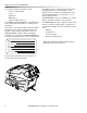
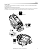
Operations Components 1. Control Panel-Drive/Scrub 9. Solution Drain Hose 2. Front Cover 10. Vacuum Shoes 3. Solution Tank 11. Chemical Tank "A" (Deluxe) 4. Recovery Tank 12. Chemical Tank "B" (Deluxe) 5. Solution Fill Cover 13. Accessory Vacuum Port (Deluxe) 6. Recovery Dome 14. Accessory Water Port (Deluxe) 7. Scrub Deck 15. Accessory Port Cover (Deluxe) 8. Recovery Drain Hose 16.
Operations 5 2 4 3 1 6 7 Drive Controls 1. Key Switch 6. Hour Meter 2. Reverse Switch 7. E-Stop Button (Deluxe) 3. Throttle Switches 4. Speed Control Knob 5.
Operations 1. Key Switch Controls the power for machine functions. To turn the machine power on, rotate key clockwise. To turn the machine off, rotate key counterclockwise. 2. Reverse Button Controls the direction of travel of the vehicle. To travel in reverse, press the button and press either of the throttle switches. To travel forward, release the button are press either of the throttle switches. 3. Throttle Switches Propel the vehicle with the speed control knob setting selected.
Operations 2 3 1 Scrub Controls 1. Solution Pump Switch 2. Solution Pump Indicator 3.
Operations 1. Solution Pump Switch Controls power to the spray pump. If the throttle is in neutral, or reverse control button is in reverse position, the flow is automatically interrupted. This feature prevents application of solution without scrubbing it into carpet. 2. Solution Pump Indicator Light The solution pump indicator light is illuminated green when the pump is on. 3.
Operations Scrub Deck Rotary Switch (Deluxe) Raises and lowers the scrub deck, and turns the scrub brush motors on and off, and controls the solution solenoids. For interim/pre-spray "A" mode, rotate the function knob to the "A" position. The "A" chemical will be drawn from its tank and delivered to the solution system. The scrub deck will lower and the scrub motor will turn on and the interim/ pre-spray solenoid will open and spray will flow through the jets.
Operations Machine Operation Emergency Stop Procedures Pre-Run Machine Inspection Do a pre-run inspection to find possible problems that could cause poor performance or lost time from breakdown. Follow the same procedure each time to avoid missing steps. NOTE: See maintenance section for pre-run machine inspection checklist items. Starting Machine NOTE: Perform pre-run machine check before operating machine.
Operations Filling Solution Tank Normal Scrubbing FOR SAFETY: Before leaving or servicing machine; stop on level surface, turn off machine and remove key. 1. Turn the machine power off. 2. Remove the front cover and the solution fill lid. 3. Fill the solution tank with clean water. (See the Technical Specifications chart for exact capacity). The water must not be hotter than 140° F (60°C) to prevent damage to the tank. 4. Replace the solution fill lid and front cover. Deluxe 1.
Operations To Begin Scrubbing To Stop Scrubbing When operating the machine around people, pay close attention for unexpected movement. Use extra caution around children. 1. While scrubbing turn off the pump switch to stop spraying solution. Continue to scrub and recover the solution for an additional pass. 2. Allow the throttle switches to return to neutral. 3. Rotate the selector switch to the accessory position so that the vacuum motor continues to run and evacuate the system.
Operations Emptying And Cleaning Chemical Tanks And System (Deluxe) 1. Turn off machine and remove front cover. 2. Park the machine next to a floor drain. The tanks are located at the front of the machine. 3. Remove the cap and straw from each chemical bottle and install the closed caps. SOLUTION DRAIN HOSE 4. Remove the tanks by lifting off the solution fill tower. 5. The chemical can remain in the tank or be disposed of properly. Remove one cap at a time and properly dispose of chemical.
Notes 86400200 Operators Manual - Commodore Duo 25
Maintenance Service Schedule Before Each Work Period Maintenance Check water level of batteries after charging; add distilled water if necessary. Check brushes for proper installation. Check for securely attached drain hose, plug and cap. Check that solution fill lid seals tightly Visually check for damaged or worn tires. Check all throttle, direction and speed controls for proper operation. Observe spray pattern and clean jets if necessary. Prime chemical system for 30 seconds for each chemical.
Maintenance 1. Battery Connector 5. "Y" Tube 2. Battery Connector 6a. Recovery Hose - Basic 3. Batteries 6b. Recovery Hose - Deluxe 4.
Maintenance Batteries (Wet Cell Only) The batteries provide the power to operate the machine. The batteries require regular maintenance to keep them operating at peak efficiency. The machine batteries will hold their charge for long periods of time, but they can only be charged a certain number of times. To get the greatest life from the batteries, charge them when their charge level reaches 25% of a full charge. Use a hydrometer to check the charge level.
Maintenance NOTE: Do not take readings immediately after adding distilled water, if the water and acid are not thoroughly mixed, the reading may not be accurate. Check the hydrometer readings against this chart. SPECIFIC GRAVITY @ 80° F (27°C) BATTERY CONDITION 1.265 100% CHARGED 1.225 75% CHARGED 1.190 50% CHARGED 1.155 25% CHARGED 1.120 DISCHARGED NOTE: If the readings are taken when the battery electrolyte is any temperature other than 80°F (27°C), the reading must be temperature corrected.
Maintenance 5. Check the electrolyte level in each battery cell. Before charging, add just enough distilled water to cover the plates. After charging is complete, add just enough distilled water to bring up the level to the indicator ring. If the water level is too high before charging, normal expansion rate of the electrolyte may cause an overflow resulting in a loss of battery acid balance and damage the machine. 6. Replace the battery caps, and leave them in place while charging. 6.
Maintenance 1 2 4 3 Scrub Deck 1. Scrub deck lift actuator 2. Scrub brush motor 3. Scrub brushes 4.
Maintenance Scrub Head Scrub Brushes The dual cylindrical scrub head is designed to scrub chemical into the carpet. The two counter rotating brushes raise the pile of the carpet, giving it a lush groomed appearance. Scrub Brush Removal The scrub brushes are removed from the right side of the machine. 1. Raise the scrub deck to the storage position. 2. Pull out on the bottom of the retaining clip. Maintenance Scrub brushes should be exchanged front to back every 50 hours to ensure even wear.
Maintenance Scrub Motor Brush Motor Carbon Brush Replacement 1. Scribe alignment mark on motor barrel to motor cap. Remove two bolts. Do not use a pressure washer to clean around the brush motors. Use tap pressure only. N’utilisez pas de nettoyeur haute pression pour nettoyer autour des moteurs des brosses. Utilisez seulement la pression du robinet. To Replace Scrub Brush Motor 1. With the scrub deck in the lowered position, remove the deck cover and disconnect brush motor wiring connector from harness.
Maintenance Actuator Scrub Deck Removal/ Replacement Scrub Deck Actuator Adjustment FOR SAFETY: Before leaving or servicing machine, stop on a level surface. Turn off machine. To adjust the actuator: 1. Lower scrub deck. Remove the front cover and raise recovery tank. 2. Disconnect electrical connector. 3. Remove the clevis pin retaining the bottom of the actuator. 4. Remove the clevis pin retaining the top of the actuator. 5. Reverse for re-installation.
Maintenance DELUXE ONLY 1 Circuit Protection 30 Amp. Protects the vacuum motor. 1. Circuit Breakers Circuit breakers interrupt the flow of power in the event of an electrical overload. When a circuit breaker is tripped, reset it by pressing the exposed button. If a circuit breaker continues to trip, the cause of the electrical overload should be found and corrected 30 Amp. Protects the vacuum motor. 22 Amp. Protects the scrub brush motor. 25 Amp. Protects the propel motor. 3 Amp.
Maintenance 1 2 3 4 5 BASIC Solution Strainer & Pump-Basic 1. Pump 4. Jets- Interim 2. Solution Strainer 5. Jets-Extraction 3.
Maintenance Solution Strainer Jets The solution strainer is located on the front of the machine under the front cover. The strainer protects the pump, solenoid valve and jets from debris. If there is little or no solution flow to the ground, check the strainer for debris. Clean the solution strainer. To remove the strainer, turn the bottom part of the strainer counterclockwise until the bottom is separated. Clean out the debris from the wire mesh and the bowl and reassemble.
Maintenance 1 2 7 6 4 3 5 3 Solution Strainer & Pump-Deluxe 1. Pump 5. Jets-Extraction 2. Solution Strainer 6. A-B Chemical Valve 3. Solenoid Valves 7. Chemical Pump 4.
Maintenance Pump Jets The pump is located on underside of the recovery tank. The pump delivers solution from the tank to the scrub deck. The two sets of jets are located in front of the scrub deck. To repair or replace pump: 1. Remove bracket assembly from the bottom side of the recovery tank. 2. Remove hoses connecting the pump. 3. Remove screws that secures pump to mounting plate. Solution Strainer The solution strainer is located under the recovery tank.
Maintenance A-B Chemical Pump & Chemical Pump 1. The chemical tank "A" holds either encapsulating interim chemical or pre-spray chemical. Tanks should be cleaned weekly. Extra chemical should be stored using the blank cap instead of the straw cap. 2. The chemical tank "B" hold the deep extraction chemical. The tank should be cleaned weekly. Extra chemical should be stored using the blank cap instead of the straw cap. 3.
Maintenance 1 2 3 2 Drive Assembly 1. Drive Assembly 2. Grease Points 3.
Maintenance Drive Assembly Drive Motor Carbon Brush Replacement Do not use a pressure washer to clean around the motors. Use tap pressure only. N’utilisez pas de nettoyeur haute pression pour nettoyer autour des moteurs des brosses. Utilisez seulement la pression du robinet. FOR SAFETY: Before leaving or servicing machine, stop on a level surface, turn off machine and remove key. 1. Disconnect batteries from machine. 2. Disconnect the electrical connection to the traction motor. 3. Remove brush cap. 4.
Maintenance 5 6 4 2 1 2 3 Vacuum 1. Vacuum Shoes 2. Vacuum Glides 3. Vacuum Shoe Retainer Knobs 4. "Y" Tube 5. Float Ball And Screen 6.
Maintenance Vacuum Shoes Recovery Tank Float Shut-Off The dual offset vacuum shoes are designed to extract soiled solution from the carpet. The plastic vacuum shoe glides minimize wear to flooring. Maintenance When water is no longer being vacuumed from the floor and the vacuum fan is operating, the ball float has engaged. The vacuum motors will not vacuum water with recovery tank full. The recovery tank must be drained. The vacuum shoes should be removed and cleaned daily to ensure maximum recovery.
Maintenance To Repair Or Replace Vacuum Motor(s) Vacuum Motor Carbon Brushes 1. Remove the front cover, drain the recovery tank. 2. Raise the recovery tank and safely engage the prop rod latch. End Cap 3. Disconnect electrical connector from the vacuum motor(s) and connecting hoses. 4. Unbolt the bracket and vacuum motor assembly and remove from tank. Carbon Brushes 5. Remove the vacuum motor from the bracket. 6. Reverse steps to install. Make sure the gaskets fit and seal properly as you reassemble.
Maintenance Transporting Machine Preparation For Loading /Unloading Trailer Pushing Machine The machine may be pushed for short distances at speeds not to exceed 5 mph. Be careful to avoid damaging machine. The machine may be pushed by hand from the rear. Before loading or unloading machine from trailer, remove vacuum shoes to eliminate interference. Scrub head must be in the up position before loading.
Maintenance Machine Troubleshooting PROBLEM No power to machine Little or no propel CAUSE Battery disconnected Battery cables corroded Faulty key switch Low battery charge Machine turned on with propel trigger not in neutral position Tripped circuit breaker Controller overheated Loose motor connection Faulty throttle circuit or potentiometer Faulty brake circuit Machine does not Faulty speed control circuit or potentiometer change speeds Forward speed only Faulty forward/reverse switch Reverse speed only
Suggested Spare Parts 86199840, FLOAT SCREEN CAGE ASM 86335930, CAP, DISPENSING, 9.50 TUBE 86335940, CAP, DISPENSING, 6.
Notes 86400200 Operators Manual - Commodore Duo 49