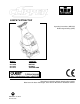
CARPET EXTRACTOR Operating Instructions (GB/USA) Bedienungsanleitung (GER) MODEL: CLP12IA CLP12IB CLP12IE CLP12IS COUNTRY AUSTRALIA BRITIAN EUROPE SWITZERLAND IPX4 Read these instructions before operating the machine Bitte lesen Sie diese Anleitungen, bevor Sie die Maschine in Gebrauch nehmen AH 86038280 07/14/14 PRV NO.
MACHINE DATA LOG Warranty Registration Thank you for purchasing a Windsor product. Warranty registration is quick and easy. Your registration will allow us to serve you better over the lifetime of the product. To register your product go to: www.windsorind.com/WarrantyRegistration.
TABLE OF CONTENTS Machine Data Log. ...............................................2 Table of Contents.................................................3 HOW TO USE THIS MANUAL How to use this Manual........................................1-1 SAFETY Important Safety Instructions ...............................2-1 Hazard Intensity Level..........................................2-2 Grounding Instructions. ........................................2-3 GROUP PARTS LIST Brush ......................................
HOW TO USE THIS MANUAL This manual contains the following sections: - The PARTS LIST section contains assembled parts illustrations and corresponding parts list. The parts lists include a number of columns of information: HOW TO USE THIS MANUAL SAFETY OPERATIONS MAINTENANCE PARTS LIST - The HOW TO USE THIS MANUAL section will tell you how to find important information for ordering correct repair parts. - Parts may be ordered from authorized Windsor dealers.
IMPORTANT SAFETY INSTRUCTIONS When using an electrical appliance, basic precaution must always be followed, including the following: READ ALL INSTRUCTIONS BEFORE USING THIS MACHINE. This machine is for commercial use. To reduce the risk of fire, electric shock, or injury: Connect to a properly grounded outlet. Do not leave the machine unattended. Unplug machine from outlet when not in use and before maintenance or service. Use only indoors. Do not use outdoors or expose to rain.
HAZARD INTENSITY LEVEL The following symbols are used throughout this guide as indicated in their descriptions: HAZARD INTENSITY LEVEL There are three levels of hazard intensity identified by signal words -WARNING and CAUTION and FOR SAFETY. The level of hazard intensity is determined by the following definitions: ! WARNING WARNING - Hazards or unsafe practices which COULD result in severe personal injury or death.
GROUNDING INSTRUCTIONS THIS PRODUCT IS FOR COMMERCIAL USE ONLY. ELECTRICAL: The amp, hertz, and voltage are listed on the data label found on each machine. Using voltages above or below those indicated on the data label will cause serious damage to the motors. EXTENSION CORDS: If an extension cord is used, the wire size must be at least one size larger than the power cord on the machine, and must be limited to 50 feet (15.5m) in length. GROUNDING INSTRUCTIONS: This appliance must be grounded.
TECHNICAL SPECIFICATIONS ITEM Electrical Electric Vacuum Motor Waterlift Brush Brush Speed Solution Pump Solution Capacity Solution Spray Recovery Capacity DIMENSION/CAPACITY 230-240V, 7A, 50 HZ (1) 3 stage, 1 hp, 99 cfm (2.80 cubic m/min.) 117” (297cm) (1) 18” (45.7cm.) 1000 rpm 100 PSI, diaphragm style, internal bypass 12 gallons (45.5l) 2 quick change jets. 12 gallons (45.5l) 20” (51 cm) cast aluminum with spring loaded down pressure (2) 10” dia. (25cm) wheels by 2” 105lbs.
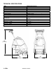
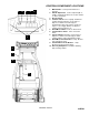
CONTROLS/COMPONENT LOCATIONS 8 9 5 4 7 2 6 1. Main Handle. Used to pull and maneuver machine. 2. Handle Adjustment. Used to adjust height of handle, and allow machine to be used in “PUSH” or “PULL orientation. 3. Electrical Cord. 4. Solution Switch. Turns on pump. Continuous position (bottom) activates electro-valve to dispense solution to floor through jets. Intermittent position (up) requires operator to depress 1 of 3 trigger switches to dispense solution. Center position is off. 5.
CONTROLS/COMPONENT LOCATIONS 1. Solution Accessory Tool Hookup. Used for various auxiliary cleaning tools. 2. Vacuum Hose Door. Used to connect various auxiliary 1 ½ inch cleaning tool vacuum hoses. 3. Brush Height Adjustment. Used to regulate brush height from storage position to various carpet heights. 4. Recovery Tank. Used to collect dirty cleaning solution. 5. Solution Tank. Used to hold cleaning solution. 6. Solution Dump Hose. Facilitates draining excess cleaning solution from solution tank. 7.
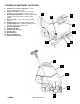
CONTROLS/COMPONENT LOCATIONS 1. 2. 3. 4. 5. 6. Solution Intake Cover. Vacuum Intake Cover. Float Shut-Off. Clean-Out Opening. Pour Spout. Lift Handle.
OPERATIONS STEP 1 STEP 2 STEP 3 1/8in (3mm) Remove electrical cord and literature from recovery tank. Fill solution tank (see filling instructions). Plug cord into grounded outlet. Note: Be sure dome is seated on recovery tank, and float shut-off is installed correctly. Adjust brush to proper setting. Note: For good operation the brush must skim the carpet. If circuit breaker trips raise brush to prevent damage to motor or carpet.
OPERATIONS Adjust handle to comfortable operating position. Tip machine back by main handle to move to starting point. STEP Lower machine to floor. STEP 5 6 STEP Select continuous setting to start solution spray or select intermittent setting to 7 enable use of trigger switches to start solution spray.
FILLING OPERATIONS STEP 1 RECOVERY TANK Remove solution tank lid SOLUTION TANK LEFT SIDE OF UNIT RIGHT SIDE OF UNIT STEP Add water 2 or 12 gal. (45.5 ltr.) 140°F (60°C) FILL LINE STEP 3 12 – 24oz. (356ml – 711ml) FILLING THE CLIPPER NOTE: Use clean bucket of water to fill solution tank Add cleaning chemical Do not put defoamer, solvents, spotter or prespray chemicals in the solution tank. Do not allow water to spill into vacuum motor inlet.
CLEANING PROCEDURE 1 1. This machine can be operated in either direction. For smaller areas operate the machine by pulling rearward. 2. For larger unobstructed areas, flip the handle and use the machine’s brush assisted propelling motion. 2 STEP 1 STEP 2 1ft. (30cm) 1in. (25mm) Start at wall closest to power outlet. For small areas, pull straight back without pushing down on handle.
CLEANING PROCEDURE Start at wall closest to power outlet. For large areas flip handle and operate machine in parallel passes, overlapping brush path. Clean perimeter last. OR STEP 1 During operation, observe the following: The Clipper is equipped with clear internal covers to facilitate operator viewing of dirty solution and STEP 4 vacuum air flow. During operation, observe the vacuum intake cover. Large amounts of water or foam entering the vacuum system can damage the vacuum motor.
CLEANING PROCEDURE STEP 7 STEP 8 To speed drying, use a Windblower™ fan. Empty recovery tank by releasing dump hose. Use a hose with cold water to clean out the recovery tank. Also drain solution tank after each use.
ACCESSORY TOOL USAGE Use only one of the following acceptable accessory tools. 86000020 – PRV NO. HT 86000000 – PRV NO. DDH 86041150 – PRV NO. DH 86031540 – PRV NO. 39504 86000610 – PRV NO. 89227 86000600 – PRV NO. 89226 STEP 1 Pull back collar and insert over machine mounted fitting, then release collar to lock into place. Lift door on front of vacuum shoe and insert STEP 1 ½ inch hose cuff into hole. 2 Turn on vacuum motor switch and set solution switch to intermittent position.
MAINTENANCE Vacuum Motor Carbon Brushes Replacement (Ametek) ONLY QUALIFIED MAINTENANCE PERSONNEL ARE TO PERFORM THE FOLLOWING REPAIRS. VACUUM MOTOR REPLACEMENT 1. Turn off all switches and unplug machine. 2. Remove recovery tank. 3. Remove the (2) screws that fasten the solution tank to the frame, and tilt tank back to expose the inside of the frame. 4. Locate the vacuum motor wires and disconnect at the connector. Close the solution tank. 5.
MAINTENANCE SOLUTION PUMP REPLACEMENT 1. Turn off all switches and unplug the machine. 2. Remove recovery tank. 3. Remove the (2) screws that fasten the solution tank to the frame, and tilt tank back to expose the inside of the frame. 4. Remove solution hoses from fittings in pump. 5. Remove the (2) screws that fasten the pump to the frame. 6. Reverse process to install pump. Pump Replacement Parts for Shurflo 100 psi (86026400 – PRV NO. 65254) Pump Head 86251040 PRV NO.
MAINTENANCE PERIODIC MAINTENANCE Twice a month, flush a white vinegar solution (One quart vinegar to two gallons of water) or antibrowning solution (mixed as directed) through the extractor. This will prevent build-up of alkaline residue in the system. If spray jets become clogged, remove the spray tips, wash them thoroughly, and blow-dry. NOTE: Do not use pins, wire, etc. to clean nozzles as this could destroy spray pattern. Periodically inspect all hoses, electrical cables and connections on your machine.
TROUBLESHOOTING CHART PROBLEM No Power, Nothing Runs Vacuum Motor Will Not Run Vacuum Motor Runs But Suction Is Poor Poor Or No Water Flow (Carpet Is Streaky) Brush Does Not Spin 4-4ENG CAUSE 1. Is the cord plugged in? 2. Circuit breaker tripped in building. 3. Faulty switch. 4. Faulty power cord or pigtail. 1. Vacuum circuit breaker tripped. 2. Faulty main vacuum switch. 3. Loose wiring. 4. Faulty vac motor. 1. Debris lodged in vac shoe. 2. Dome gasket defective or missing. 3.
NOTES 86038280 04/04/07 4-5ENG
BRUSH 31 15 25 11 7 25 29 30 8 16 12 26 24 38 18 39 10 22 16 30 34 4 44 45 36 47 40 37 41 33 26 32 17 28 35 3 43 13 21 42 27 6 1 19 14 17 23 20 30 25 29 25 46 3 9 2 5 5-1 86038280 04/04/07
BRUSH REF PART NO. PRV NO.
CONTROL PANEL 18 19 4 49 10 37 46 22 47 38 33 3 16 45 43 2 50 41 1 28 40 39 8 9 31 7 21 11 45 44 23 27 42 15 30 24 42 20 6 35 34 C 3 6 A, 3 6 B , 3 6 C , 36 D (S E E F R A M E ) 32 26 12 17 29 5 13 14 48 45 25 5-3 86038280 08/29/13
CONTROL PANEL REF PART NO. PRV NO.
FRAME 33 7 19 18 15 (SEE SOLUTION TANK) A 21 B 12 34 11 10 C 3 6 5 (SEE CONTROL PANEL) 22 26 32 9 35 2 20 8 16 27 16 28 8 4 13 20 29 5-5 24 25 30 86038280 07/14/14 14
FRAME REF PART NO. PRV NO.
PUMP 3 20 29 29 17 4 13 28 10 16 8 2 16 21 23 18 1 12 19 15 20 11 22 26 9 7 25 25 22 D 6 (SEE SOLUTION TANK) 26 5-7 24 27 86038280 04/04/07 5
PUMP REF PART NO. PRV NO.
PUMP PRIOR TO S/N 1000153174 8 3 29 20 29 17 13 4 28 10 16 2 16 21 23 18 1 12 19 15 20 11 9 7 25 26 30 D 6 5 (SEE SOLUTION TANK) 26 5-9 24 27 86038280 04/04/07
PUMP PROIR TO S/N 1000153174 REF PART NO. PRV NO.
RECOVERY TANK 16 15 5 E 18 7 11 4 12 8 10 E 1 14 13 9 12 17 2 6 11B 3 10B 1B 14B 12 5-11 86038280 04/04/07
RECOVERY TANK REF PART NO. PRV NO. QTY 1A 1B 2 3 4 5 6 7 8 9 10A 10B 11A 11B 12 13 14A 14B 15 16 17 18 86002400 86002350 86233140 86002930 86003110 86235280 86003630 86003910 86003930 86004200 86004510 86004450 86004500 86006240 86006600 86032290 86001370 86001190 86002870 86242230 86245920 86003330 20064 20002 20041 27670 27816 28060 34351 35230 35232 39353 41391 40019 41390 66227 70114 75262 140408 140133 27417 500009 50993 28061 1 1 1 1 2 1 1 1 2 1 1 1 1 1 6 1 1 1 1 1 1 1 DESCRIPTION SERIAL NO.
SOLUTION TANK 6 13 3 16 7 10 12 12A 12B 20 15 11 7* (SEE FRAME) A 26 14* 30 29 24* 8 27 19 18 9 2 1 17* 23* 21* 32 22* 28 5* B D (SEE FRAME) 4 (SEE PUMP) 16 25 5-13 86038280 12/14/09
SOLUTION TANK REF PART NO. PRV NO. QTY DESCRIPTION 1 2 3 4 5 6 7 8 9 10 11 12 86233140 86233150 86003080 86003090 86235500 86003790 86003920 86281880 86240100 86004340 86240980 86005420 20041 20042 27809 27810 31081 35175 35231 39526 39536 39528 41348 53791 2 1 1 1 1 2 2 1 1 REF 1 1 CLAMP, 2.0" WORM GEAR CLAMP, 3/8 HOSE (D-SLOT) COVER, VAC MOTOR COVER, BELT ELBOW, 3/8 MPT X 3/8 TUBE, PLASTIC GASKET, TANK TO VAC COVER GASKET, VAC COVER (CLP FAMILY) HOSE,1/2 CLEAR X 12 HOSE, 1.5 BLK VAC X 5.
VACUUM SHOE 1 4 11 7 13 10 2 12 3 5 8 6 7 11 5-15 86038280 04/04/07
VACUUM SHOE REF PART NO. PRV NO. QTY 1 2 3 4 5 6 7 8 9 10 11 12 13 86227350 86234760 86005810 86006790 86275120 86006840 86008130 86258630 86010630 86010700 86003780 86008120 05016 27674 57245 70351 70360 70390 73958 85040 OPEN 87013 87074 35171 73955 4 1 4 2 4 4 8 1 4 8 1 2 DESCRIPTION SERIAL NO. FROM NOTES: ARM, VAC SHOE PARALLEL COVER, ACCESSORY PORT NUT, 1/4-20 HEX NYLOCK SS SCR, 10-32 X 3/8 HHTR W/STAR SCR, 1/4-20 X.75 PPHMS PHIL SCR, 1/4-20 X 1 FHCS PLTD SPACER, 3/8ODX.058WX.
WIRING DIAGRAM 86268929 PRV NO. 88229 86268430 PRV NO. 88323 86003650 PRV NO. 34362 86238840 PRV NO. 41356 86238830 PRV NO. 41355 86268900 PRV NO. 88655 86268430 PRV NO. 88276 86266720 PRV NO. 880043 86268460 PRV NO. 88333 86238820 PRV NO. 41351 86268420 PRV NO. 88317 5-17 86038280 04/04/07 86268750 PRV NO.
SUGGESTED SPARE PARTS SERIAL NO. NOTES: FROM PART NO. PRV NO. DESCRIPTION 86001150 86001100 86000900 86004570 86004580 86026400 86010570 86003780 86230110 86002020 86007140 86007200 86005370 86007970 86003330 86003630 86006240 86230760 86235330 12515 11045 09019 44067 44068 65254 84165 35171 14312 14949 72130 72162 53641 73864 28061 34351 66227 140216 140688 BRUSH, 18L X 3.38OD BELT, 180J6 MICRO-V BEARING, 1.125ODX.500IDX.
5-19 86038280 04/04/07